|
|
Rules Editor  : Size Rules
Access: Open this function from the following location:
-
Select Catalog > Catalog Part Definitions > Edit Add Rules from the menu bar.
Edit the rules used when adding components.
When adding a catalog component, you can apply certain rules regarding the location and/or size of the added components, by using the Add Rules functionality. The Rules Editor is an editing tool that enables you to add new rules, delete rules or modify existing rules.
InvokeInvoke the Rules Editor to display the Rules Editor dialog showing information about the catalog and any existing rules in the Size tab:
|
|
Add Rules are divided into two categories, Location (Placing) Rules and Size Rules. Size Rules:
|
Up to 4 size parameters can be related, with each parameter having its own dialog interaction.
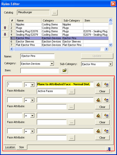
For example, in the dialog above showing the Size tab, the rule states the following:
- The rule refers to the Meusburger catalog.
- The name of the rule is Ejector Pins and it applies to the whole sub-category of ejector pins.
- The rule determines that the length of the ejector will be bigger than the distance between the placement plane and active faces, as measured by a normal to the placement plane at the point of placement.
- In this case, since the length of ejector is named "l" in all Meusburger ejectors, the size rule is applicable to all.
Additional Examples:Additional Examples:
The rule below states that the diameter of "d1" (in this case a plug) shall be bigger than the cooling face diameter.

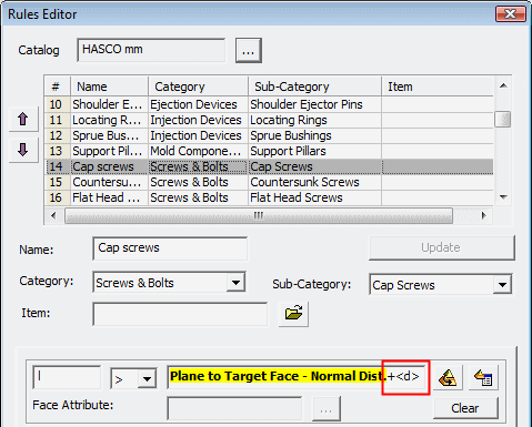
The rule below states that the length "l1" (in this case a cap screw) shall be longer from the distance between placement plane and the selected target face, as measured by a normal to the placement plane at the point of placement.

Notes:
-
The components will NOT be associative to size rules; however, they will stay linked to location rules.
-
Each catalog brand (such as "Hasco", "DME" or "Misumi") has its own set of rules.
-
The rules may be applied on a category, sub-category or a specific item. This means, for example, that all components in a catalog category or all components which are assigned to a sub-category (e.g. the Ejector Pin sub-category) can have the same rule. Individual catalog items can have specific rules assigned to them.
-
Rules per each catalog brand are predefined by the system; however, the Rules Editor is an editing tool that enables you to add new rules, delete rules or modify existing rules.
Size Rules Parameters
|
Parameter Name field: |
Type in a unique parameter name (one that has not already been used in this rule). If the parameter name already exists in the rule, an appropriate message is displayed.
|
||
|
Relation Type field: |
Select an appropriate relation type from the dropdown list.
Available types are as follows:
|
||
|
Expression field: |
Expressions are created by adding geometrical/setup parameters as "rigid text" to the expression box by using the
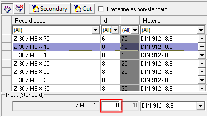
In addition, you can also have size rules dependent on other dimensions in the same catalog, as shown below. In the example below, the length of a screw "l" is dependent on its diameter "d":
This dependency will work only if "d" has been explicitly specified by clicking a row or by typing in a value when the catalog component (in this case the cap screw) is selected, as shown below:
Note: A tool tip showing the complete expression name is displayed by placing the cursor in the expression box. This is useful for expressions that are longer than the box length, for example: |
||
|
|
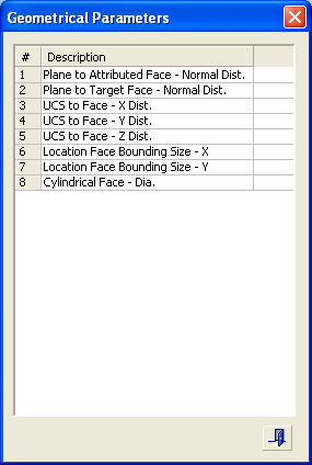
Add geometrical parameters to expressions. This button displays the Geometrical Parameters dialog showing the available parameters. Double-click a row in the dialog to add "rigid text" it to the expression box.
The geometrical parameters use the contents of the Face Attribute field defined per relation. For example, when a Plane to Face relation is used, the type of face is indicated in the corresponding Face Attribute field, see below. All geometrical parameter rules can be used in a relation together with setup parameters. Press ExitExit to close the dialog. |
||
|
|
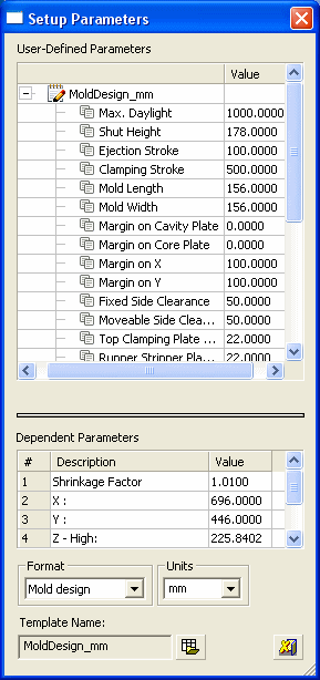
Add setup parameters to expressions. This button displays the Setup Parameters dialog showing the available parameters. Double-click a row to add "rigid text" it to the expression box. See Relating Setup Parameters for additional information regarding using the setup parameters in relations.
All setup parameter rules can be used in a relation together with geometrical parameters. Press ExitExit to close the dialog. |
||
|
Face Attribute field: |
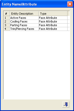
The face attribute is used with the Geometrical Parameters to indicate a specific type of face. For example, when a "Plane to Face" relation is used, the type of face is indicated in the corresponding Face Attribute box. The browse button displays the Entity Name/Attribute dialog showing the available faces. Double-click a row to add "rigid text" it to the Face Attribute field. Alternatively, you can directly type in a face type or delete it to clear the field.
Press ExitExit to close the dialog. |
||
|
Clear |
The Clear button clears the specific size rule. |
Notes:
-
One rule set can contain many size and locating rules.
-
Each rule takes the full path name of the component to be added and the target location.
-
Make sure that the selected component or entity has a name attached to it.
|



 and
and  buttons respectively. Alternatively, you can directly type in expressions or delete it to clear the expression.

