|
|
Show Analysis  : Options and Results

Access: Open this function from one of the following locations:
-
Select Die Design > Blanking Tools > Show Analysis from the menu bar.
-
Select Show Analysis from the following Die Design Guide: Die Process Design Guide (Forming).
Show the results of the finite element analysis (such as thickness strain and safety zone ranges) on a part where a blank has been created. This function can only be used on a file where a blank has already been created.
Notes:
-
Create a Blank before using the Show Analysis function. Blanks can be created on the following functions, Auto Blank on Binder, Blank, Blank on Binder or Local Blank.
-
The analysis is always done on the last blank created.
-
The edit capabilities are not relevant for this function. Since it used only for viewing data. However, you can re-enter the function at any time to select and view a different data analysis option.
Required Step 1 
- Select the appropriate option to view the analysis. The following options are available in a dropdown list:
None
When this option is selected, no data analysis is displayed.
Example:Example:
Thickness Strain Analysis
Perform a thickness strain analysis and display the thickness strain ranges as shown below. This option enables evaluating the formality of stamping. A negative value indicates the part is thinning out. Severe thinning indicates splitting can occur and thickening indicates wrinkling can occur.
Example:Example:
Notes:
-
You can move the mouse over the part to get detailed information regarding a specific area, as shown in the example above.
-
Set the upper and lower limit range of the analysis in the Die Preferences.
Safety Zone Analysis
Perform a safety zone analysis and display the safety zone ranges as shown below. The safety zones range from Low Strain to Fail and are described below.
Example:Example:
The meaning of each safety zone is detailed below:
Strong Wrinkle Tendency
Slight stretch in one direction and compression in the other with material thickening. In this case, wrinkles are very likely to occur.
Wrinkling Tendency
Stretch in one direction and compression in the other with slight material thickening. In this case, wrinkles may occur.
Low Strain
Minimal stretch or compression in either the major or minor directions.
Safe
This is the area below Forming Limit Curve where failure is not likely to occur.
Marginal
This is the area between the Safe and Fail zones where the forming process is marginally safe.
Fail
This is the area above Forming Limit Curve where splitting is likely to occur (localized thinning).
Note: You can move the mouse over the part to get detailed information regarding a specific area, as shown in the example above.
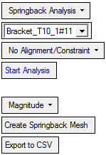
Springback Analysis
Perform a springback analysis and display the results according to the options selected. See Springback Analysis below.
Springback Analysis
The springback effect often causes a lengthy and costly iterative process of design, tool manufacture, and trial on the shop floor. This Springback Analysis option allows designers to undertake iterations on their computers, rather than having to manufacture and test the tool on the shop floor.
The Springback Analysis estimates the effect of the springback considering the shape, constraints and material properties. An object showing the result of the springback deformation can be created as an STL model. Deform values are provided and are shown on a color map; these values can then be transferred to the Springback Deform function in order to modify (compensate) the shape of the tool.
The following parameters are displayed (any previous analysis (Thickness Strain or Safety Zone) is cleared):
<Part Name>
This parameter is only displayed if the analysis is performed on a part in an assembly file.
This is a dropdown list of the parts in the assembly that have thickness analysis data (where a Blank operation has been performed), with the display showing the name of the part on which the Show Analysis operation is being performed.
No Alignment/ Constraint
This is a dropdown list enabling you to select alignment or constraint options for the analysis.
Examples of Alignment/Constraint analysis results:Examples of Alignment/Constraint analysis results:No Alignment/Constraint
Springback Analysis result:3 Points Alignment
Springback Analysis result:Constraint Edges/Points
Springback Analysis result:The blue color shows an area where there is almost no movement of the material due to the bending of the geometry (as defined by the alignment/constraint in the highlighted areas - see the explanations below).
The following alignment or constraint options are available:
No Alignment/ Constraint
No alignment or constraint is defined.
Example:Example:3 Points Alignment
Realign the springback "mesh" with respect to the original skin. This operation does not change the shape of the springback mesh, it only changes the position. The alignment is based on rigid body motion.
The following parameters are displayed:
The toggle option Fix First Point / Don't Fix First Point is displayed. If you select the Fix First Point option, it forces the first point to be coincident between the part and springback mesh.
Using the
 button, pick 3 alignment points that lie on the selected faces and then <exit><exit>.
Three points are picked on the surface of the geometry where the movement during the bending of the part is to be almost zero.
Springback Analysis result: The blue color shows an area where there is almost no movement of the material due to the bending of the geometry (as defined by the three points).
Constraint Edges/Points
Define constraint edges and or points for the analysis.
The following parameters are displayed:
Using the
 button, pick edges or points (or wires/curves) that lie on the selected faces and then <exit><exit>.
A constraint edge is picked on the surface of the geometry where the movement during the bending of the part is to be almost zero.
Springback Analysis result: The blue color shows an area where there is almost no movement of the material due to the bending of the geometry (as defined by the constraint edge).
Start Analysis
Start the springback analysis based on the selected parameters.
Magnitude
This is a dropdown list enabling you to select the following options for the analysis:
Note: For each analysis result option, You can move the mouse over the part to get detailed information regarding a specific area, as shown in the examples above.
Magnitude
Analyze and display the total displacement. This is the default option.
Example:Example:
If this option is selected, the Create Springback STL option appears, see below.
Deflection
Analyze and display the projection of the Magnitude (vector + size) on the Normal of the face at each testing point.
Example:Example:
Component X
Analyze and display the movement of each node/triangle in the X axis direction.
Example:Example:
Component Y
Analyze and display the movement of each node/triangle in the Y axis direction.
Example:Example:
Component Z
Analyze and display the movement of each node/triangle in the Z axis direction.
Example:Example:
Create Springback Mesh
Create Mesh results for springback.
Example:Example: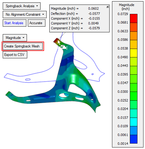
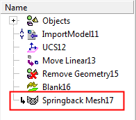
When this option is pressed a dialog is displayed requiring confirmation to create a feature. Upon confirmation, a new feature appears in the Feature Tree, as shown below. This feature reflects the Mesh data of the springback results.
Export to CSV
To be able to use the springback analysis data to deform/compensate the body being analyzed, save the before and after pair of points to a CSV file.
When this option is selected, the system displays the Save As dialog enabling you to save the .CSV file.
-
- When finished, click the Close
 button from the Feature Guide to exit the Show Analysis function.
|