|
|
Solid Extension : Options and Results


Access: Open this function from one of the following locations:
-
Select Electrode > Geometry > Solid Extension from the menu bar.
-
Select Solid Extension from the Electrode Guide.
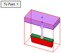
Create a solid extension on top of the solid body (the solid body created by the Burn Body function).
The Burn Body and Solid Extension functions enable you to create a body and extend it all the way up to the electrode base. Together, these functions enable you to create electrodes using solid tools.
The Solid Extension function is very similar to the Electrode Extensions function.
Note: This function is only available when an electrode is active in an assembly environment.
Required Step 1 
Pick the top face(s) of the solid body(ies) from which to extend.
By default, the system automatically selects all the top faces of the lumps (the solid bodies created by the Burn Body function) and jumps to the next stage. You can, however, return to this stage and change the selection. If no top faces are found automatically, the system remains in this step until the top face(s) are manually selected.
If the top face(s) are manually selected, press <exit><exit> to continue to the next step.
Required Step 2 
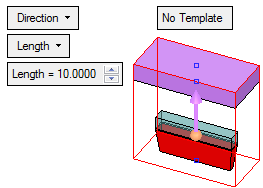
Select the extension options and set the parameters. The direction arrow is displayed to define the extension direction.
|
Direction |
This is a toggle option Direction / Tangent that enables you to define the extension direction, together with the direction arrow.
|
||||||||||||||||||||||
|
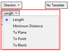
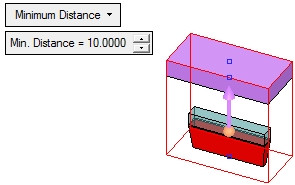
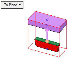
Length |
This is a dropdown list of the available extension options:
|
||||||||||||||||||||||
|
Apply Template |
This is a toggle option Apply Template / No Template that enables you apply a predefined electrode template to the electrode while it is being created. |

Optional Step 1 
Create steps before a direction extension. If all the curves in the contour lie on the same plane, a step may be created. This is a surface between the defined contour and an offset of it.
See Step Extension.
Optional Step 2 
Apply a draft angle to the extension faces. The draft angle tilts the faces from the extension direction.
Click OKOK![]() or ApplyApply
or ApplyApply![]() in the Feature Guide to complete the function.
in the Feature Guide to complete the function.
When completed, the Solid Extension feature will appear in the Feature Tree as follows:

|