|
|
Stretch  : Options and Results
Access: Open this function from the following location:
-
Select Solid > Warp > Stretch from the menu bar.
Stretch or shrink an object (and wire bodies) along a vector relative to a reference plane.
This function enables stretching and compressing any type of object or objects (such as, solid, skin, curve, composite and so on) under specific conditions along a predefined vector. Entire bodies or partial body regions can be stretched or shrunk.
Required Step 1 
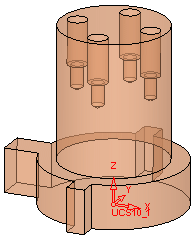
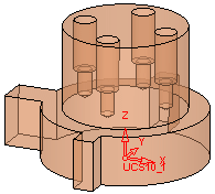
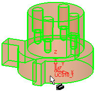
Select the object or objects that you want to stretch (or shrink) along a vector relative to the reference plane.
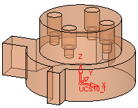
| Example part: | Object selected: |
 |
 |
Required Step 2 
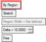
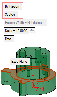
Define the stretching region and set the required parameters. Depending on the toggle option selected, the following parameters are displayed:
|
|
|
|
Parameters
|
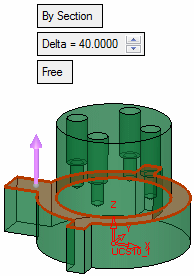
By Section |
This a toggle option By Section / By Region that enables you to define the area to be stretched/shrunk.
|
||||||||||||||||||||
|
Stretch |
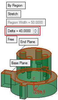
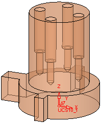
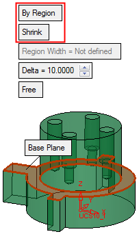
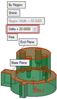
This is a toggle option Stretch / Shrink that enables you to stretch/shrink the entity as required. This option is displayed when the By Region option is selected above. See the examples in the By Section option, above. |
||||||||||||||||||||
|
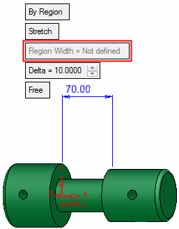
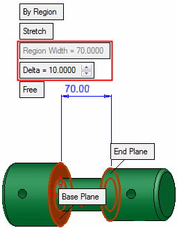
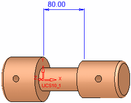
Region Width |
This is a system generated parameter and is defined by the selected base and end planes. This option is displayed when the By Region option is selected above. See the examples below and also in the By Section option, above.
|
||||||||||||||||||||
|
Delta |
The delta distance of the stretch or shrink. |
||||||||||||||||||||
|
Free |
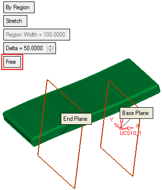
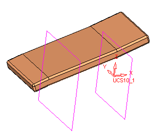
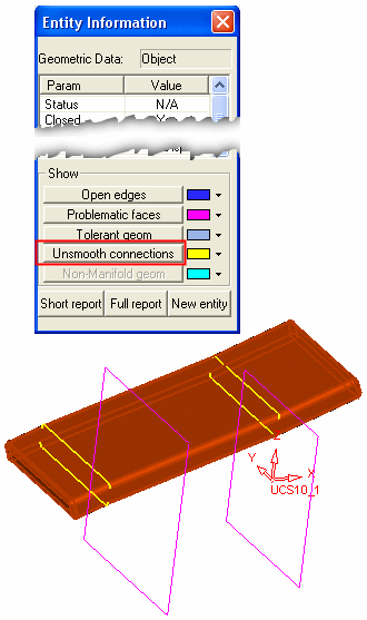
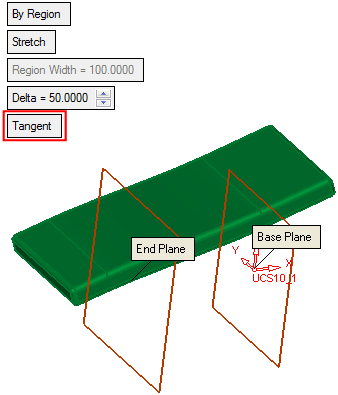
This is a toggle option Free / Tangent that defines the type of stretch/shrink performed. With the Tangent option, unsmooth connections between faces do not exist. See the Free and Tangent examples below. |
Click OK ![]() or Apply
or Apply ![]() in the Feature Guide to complete the function.
in the Feature Guide to complete the function.
Free and Tangent Examples
Free
|
1. Select the Base Plane and End Plane, define a delta value of 50, and ensure Free is selected, as follows:
|
|
2. Click OK
|
|
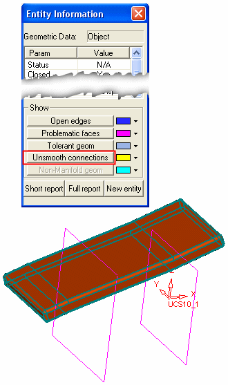
3. From the Analyze menu select Entity Information, select the Filter Objects
|
|
1. Select the Base Plane and End Plane, define a delta value of 50, and select Tangent as follows: |
|
2. Click OK |
|
3. From the Analyze menu select Entity Information, select the Filter Objects |
Click OK ![]() or Apply
or Apply ![]() in the Feature Guide to complete the function.
in the Feature Guide to complete the function.
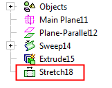
When completed, the Stretch feature will appear in the Feature Tree as follows:
|


