|
|
Special Shaped Cutters 

Access: Open this function from one of the following locations:
The Cutters and Holders dialog (or the minimized version - the Select Only Mode):
-
When not editing or creating a procedure, select NC-Process > Cutters > Cutters from the menu bar or select Cutters
in the NC Guide Toolbar. -
While editing or creating a procedure, use one of the following methods (in both methods, the Select Only Mode is displayed):
-
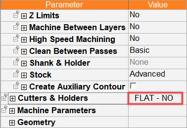
In the Advanced Mode, click on the cutter name in the Procedure Parameter Table.
-
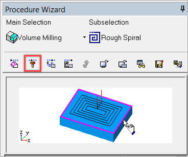
In the Wizard Mode, select the cutter button.
-
-
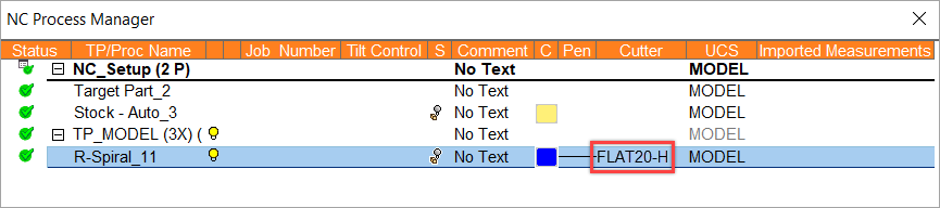
In the Process Manager, click on the cutter name in the procedure row (in this case, the Select Only Mode is displayed).
Cimatron can be configured with custom shaped user-defined cutters. It is frequently advantageous when a specific shape is required to create a special cutter to machine the area instead of using multiple cutters with multiple passes and requiring a 5X CNC machine.
In the example below, a specific shape is required for one of the edges and a new cutter needs to be defined.
|
The stock with the special edge. |
A new user-defined cutter needs to be created to machine this edge. |
|
|
|
This custom cutter can be defined in the Cutter Parameters tab of the Cutters and Holders dialog.
Basic steps for creating a user-defined cutter
-
Design the required cutter shape and create a revolved body out of the design. In the example below, the required cutter shape is outlined.
In the example below, the required cutter shape is outlined.
Create a revolved body from the design.
-
Define the revolved body as a cutter (from the Cutter Parameters tab of the Cutters and Holders Dialog).
-
Set the location of the cutter tip (from the Cutter Parameters tab of the Cutters and Holders Dialog).
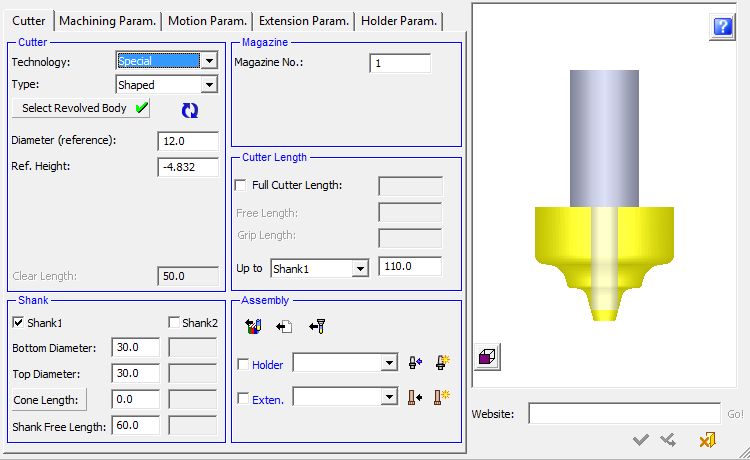
Defining a special shaped cutter
-
UseUse the Cutters and Holders dialog.
-
In the Technology field, select Special from the dropdown list of options.
-
In the Type field, select Shaped from the dropdown list of options.
-
Set the relevant parameters. As usual, the parameters that appear in the dialog are dependent upon the Technology and Type options selected. In this case, the option specific parameters:
-
Ref. Diameter
The reference diameter used to calculate the toolpath offset from the contour for 2.5-axis functions.
-
Ref. Height
The reference height used to set the toolpath at a height different from that of the height of the contour; for example, for chamfering tools.
-
- In addition, the following parameters need to be set:
-
All shaped cutters need to have a defined shank.
-
The Clear Length is set to be the length of the revolved solid. The Full Cutter Length must be longer than the Clear Length.
-
-
These and other parameters are shown below with the example cutter.
The outline of the required cutter showing the dimensions.
The same image as on the left, with the finished cutter inserted for clarity.
-
Press the Select Revolved Body button and select a previously created revolved body that will be used as the cutter (see the basic steps above, for creating a user-defined cutter).
Select the revolved body.
The 3D shape of the cutter is automatically created according to the following:
Note: If the current file does not contain a revolved body, the Select Revolved Body button is unavailable.
-
Set the location of the cutter tip. In some cases, due to its shape, the revolved body may not be orientated correctly to the shank (in the 3D representation).
-
In this case, click Flip Tool Tip Side
 to flip the revolved body to the correct orientation as shown below:
The revolved body is orientated incorrectly.
Click
to flip and correct the orientation.
-
Click OK
 to approve the definition.
 -
Use the new user-defined custom shaped cutter in a procedure.
|