|
|
Import Shaped Holder 
![]()
![]()
Access: Open this function from one of the following locations:
The Cutters and Holders dialog (or the minimized version - the Select Only Mode):
-
When not editing or creating a procedure:
-
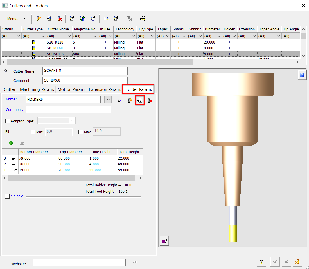
Select NC-Process > Cutters > Cutters from the menu bar. The Cutters and Holders dialog appears. Select the Holder Param. tab and click on the Import Shaped Holder button
or -
Select Cutters
 in the NC Guide Toolbar. The Cutters and Holders dialog appears. Select the Holder Param. tab and click on the Import Shaped Holder button .
-
-
While editing or creating a procedure, use one of the following methods (for both methods, the Select Only Mode is displayed):
-
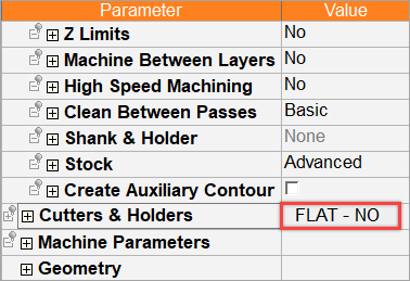
In the Advanced Mode, click on the cutter name in the Procedure Parameter Table.
-
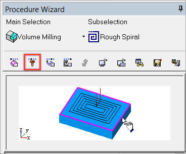
In the Wizard Mode, select the cutter button.
-
-
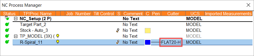
In the Process Manager, click on the cutter name in the procedure row (in this case, the Select Only Mode is displayed).
Import a shaped holder from the Holder Parameters tab in the Cutters & Holders dialog.
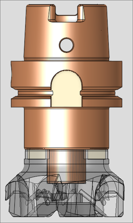
The Import Shaped Holder feature allows the import of a shaped holder's geometry from a CAD file. Cimatron automatically imports and analyzes the geometery of the shaped holder to create a new shaped holder in the Cutter Table, saving time and reducing human error versus manually creating the holder.
Importing a shaped holder
-
Click the Holder Parameters tab then click Import Shaped Holder
.
The Cimatron Explorer dialog is displayed. -
Select the file type and/or filename that you want to import. The holder is displayed in the graphics pane.
-
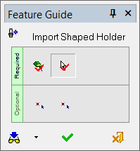
Use the Import Shaped Holder Feature Guide to define the Required steps (and Optional steps if required).
-
Required Step 1
From the Feature Guide, clickclick the Select Objects icon
 to select the object or objects (if more than one exists).
 Note: When you import a shaped holder, Cimatron automatically selects the object for you. In other words, Cimatron automatically executes Required Step 1 for you. If there is more than one object, you can modify this selection by pickingpicking the Select Objects icon
and making your selection before proceeding to Required Step 2 below. -
Required Step 2
Pick the Select Z-Axis Direction and Holder Bottom Point icon
 to define the Z-Axis direction and holder bottom point location.
 Note: By default, Cimatron uses the Z+ axis as the default direction.
-
Optional Step 1
This step is useful when the cutter top is not aligned to the lowest point of the holder, making it impossible to implement without cutting the holder (click to see the exampleexample)
Define the Holder Bottom Point where all geometry below the selected point will be cut off and the holder will start at that height.
-
From the Feature Guide's Optional steps, select the Selected Point Represents the Holder Bottom Point icon
 .
. -
Navigate to the Holder Bottom Point screen parameter
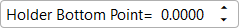 in the graphics pane and enter a value.
-
-
Optional Step 2
Define the Holder Top Point (this must be above the Holder Bottom Point defined in Required Step 2).
-
From the Feature Guide's Optional steps, select the Selected Point Represents the Holder Top Point icon
. -
Navigate to the Holder Top Point screen parameter
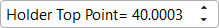 in the graphics pane and enter a value.
-
-
-
When you have finished defining the Feature Guide Required Steps (and Optional steps if needed), select Preview
 to preview or OK
  to save and close the Feature Guide.
 -
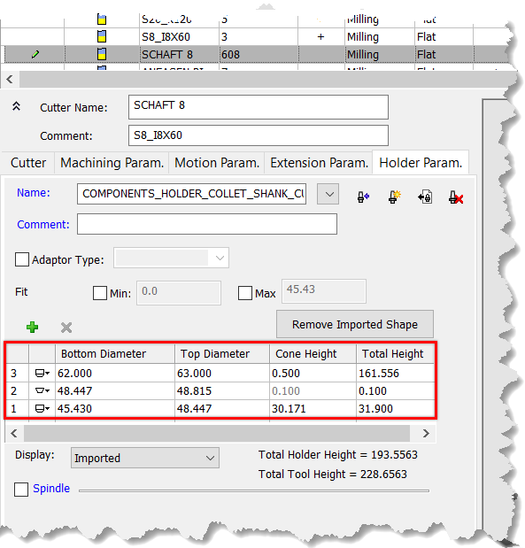
The Cutters & Holders dialog is displayed. Customize the holder settings as needed (Bottom Diameter, Top Diameter, Cone Height, and Total Height).
-
Use the Display dropdown menu to select how the holder is displayed in the dialog.

The Display options are-
Imported - Displays the holder exactly as indicated from the imported holder file's geometry.
-
Used for Calculations - Displays the holder as interpreted by Cimatron.
-
Both - Uses both the imported geometry and Cimatron geometry interpretation to display the holder.
-
-
Select OK
to save the new holder.
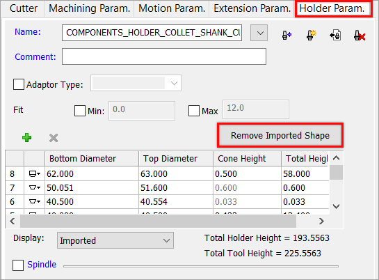
Remove Imported Shape Option
You can remove the 3D shape of a holder by using the Remove Imported Shape feature.
-
From the Holder Parameters tab, click Remove Imported Shape.
-
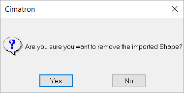
In the subsequent confirmation dialog, click Yes to proceed.
See also
|