|
|
UCS Center of Geometry 


Access: Invoke this function from one of the following locations:
-
Click the
button in the toolbar. -
Select Wireframe > Datum > UCS Center of Geometry from the menu bar.
Create a UCS positioned in the center (or on center points) of a bounding box of picked geometry.
|
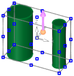
Pick the geometry: |
The new UCS is created: |
|
|
|
|
Demo: Press the button below to view a short movie demonstrating the function: |
|
|

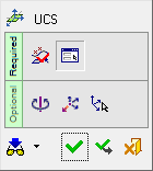
General Interaction
The following is the Feature Guide for UCS Center of Geometry.
|
|
Remember: You can open the Feature Guide at any time on the graphic display by right-clicking. |
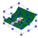
Required Step 1 
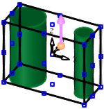
Pick the required faces or curves and <exit><exit>. In this example, both objects have been picked using the box selection.
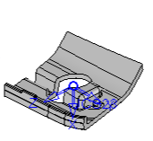
Required Step 2 
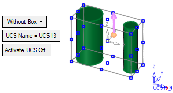
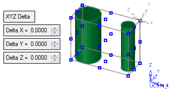
A temporary bounding box is displayed around the picked geometry, and reference points are displayed in the corners of the box and at the center of each face of the box. A UCS is created in the center of this box (the center of the picked geometry). This UCS is orientated according to the active UCS.
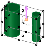
If required, pick any point to set a new UCS origin and/or click the point of the arrow to flip it or the base of the arrow to set a new direction.
The following parameters are displayed:
|
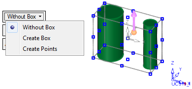
Without Box |
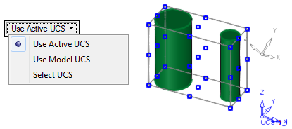
This is a dropdown list containing the following options:
|
The following parameters are also displayed:
UCS Name |
The name of the UCS being created. Click this parameter to edit the name. |
Activate UCS Off |
This
is a toggle option Activate
UCS On / Off, which enables you to activate (or not) the UCS
being created. Note: In NC operations, the default is set in the NC UCS Preferences (in the Activate Created UCS parameter). |
Optional Step 1 
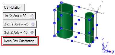
Rotate the UCS by entering the X,Y, and Z rotation values. The UCS is reorientated accordingly.
The following parameters are displayed:

|
Keep Box Orientation |
Keep the current orientation of the bounding box irrespective of the orientation of the UCS. (The orientation of the UCS is based on the XYZ rotation values).
|
|
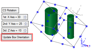
Update Box Orientation |
Re-orientate the bounding box according to the orientation of the new UCS. (The orientation of the UCS is based on the XYZ rotation values.)
|
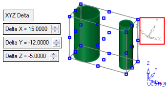
Optional Step 2 
Set the X,Y, and Z delta offset values. The UCS is moved accordingly.
|
|
|
Optional Step 3 
Define the Z direction of the UCS according to the Active UCS, Model UCS or pick any UCS belonging to the active part.
If the UCS creation is complete, press OK ![]() or Apply
or Apply ![]() in the Feature Guide.
in the Feature Guide.
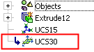
When completed, the UCS feature will appear in the Feature Tree as follows:

|