|
|
UCS (User Coordinate System) Creation


Access: Select Wireframe > Datum from the menu bar and then select the required UCS option from the UCS dropdown list.
Create one or more User Coordinate Systems (UCSs). Every file contains a default UCS; additional UCSs can be created and positioned as required.
UCSs are used for orientation, to define direction, attach components in an Assembly operation, and many other operations. As every Cimatron file contains a default UCS, this function is only needed to define new UCSs.
An example of a Geometry UCS as displayed in a Cimatron file is shown below:
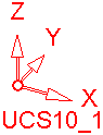
Each UCS (including the default UCS) is displayed in the orientation of the view and also shows the specific UCS name (in the example above, the UCS name is UCS10_1).
When defining a UCS:
-
A number of options are available to enable you to position the UCS as required (see below).
-
The size of the displayed UCS can be defined in the Preferences (under Tools > Preferences > General > UCS).
-
The UCS Manager enables you to perform a number of operations on UCSs.
Notes:
-
Besides defining the location of a UCS (see below), you can also set the size of the displayed UCS (under Tools > Preferences > General > UCS).
-
In the Part application, UCS is an Immediate Function, which means that it can be accessed independently or from within another part / assembly function (see the example).
-
In the MoldDesign application, use the Work CS function to create the main UCS of the mold.
-
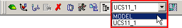
In the NC Application, once a UCS has been created (see the Interaction below), you can define the active UCS by selecting it from the NC toolbar.
Examples:Examples:
Creating a UCS - Detailed Interaction of all Options
A number of options are available to enable you to create and position the UCS as required. The Feature Guide and interaction for each function depends on the method used to create the UCS:
|
|
Create a UCS by defining an origin point and two axes. |
|
|
|
Create a UCS by picking geometry (points and/or edges). |
|
|
|
Create a UCS positioned in the center (or on center points) of a bounding box of picked geometry. |
|
|
|
Create a UCS by copying an existing UCS. |
|
|
|
Create a UCS to be used as a layout UCS and have work parts placed on it. |
|
|
|
Create a UCS by mirroring an existing UCS. |
|
|
|
Create a UCS by defining a plane that will be normal to its Z axis. |
Once a UCS has been created, you can edit it, activate it, and use it for all relevant operations.
|