|
|
Work CS 


Access: Open this function from one of the following locations:
-
Select Parting > Layout Tools > Work CS from the menu bar.
-
Select Parting Layout Tools > Work CS from the Mold Design Guide Toolbar or Parting Guide Toolbar.
Create the main reference UCS (Work CS) in the work part, defining the position of the work part in the assembly.
The Work CS is the UCS created within the work part and is the UCS by which the work part is placed in a mold (the Work CS is placed coincident to the picked layout UCS). The function creates a Work CS at the center of geometry by default; however, another UCS or the center of gravity can also be defined as the Work CS.
The following is the Feature Guide for Work UCS.
|
|
|
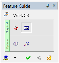
The interaction is similar to that for UCS - Center of Geometry with the following important differences:
When using Work CS, the system automatically selects all relevant faces and calculates the UCS location. In Mold Design, the relevant faces are those belonging to the work part.
At the end of the process, the feature created by the Work CS function is called Work CS<number>.
If you run Work CS a second time, the system locates the created Work CS and enables you to edit it. A new Work CS is not created.
Required Step 1  – Pick Faces/Curves
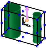
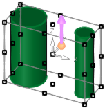
The system automatically selects all relevant faces and calculates the UCS location. The relevant faces are those belonging to the work part. Objects may also be picked manually.
Even though the system automatically selects all the relevant faces and moves to the next step, you can return to Step 1 and manually pick the required entities and then exitexit. The image below show the manual selection of both objects using the box selection.
Required Step 2  – Pick a UCS Point
-
Pick the origin point of the Work CS or a UCS to be copied.
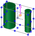
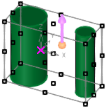
A temporary bounding box is displayed around the picked geometry, and reference points are displayed in the corners of the box and at the center of each face of the box. A UCS is created in the center of this box (the center of the picked geometry). This UCS is orientated according to the active UCS. -
If required, pick any point to set a new Work CS origin, pick another UCS whose origin will be the origin point for the Work CS, and/or click the point of the arrow to flip it or the base of the arrow to set a new direction.
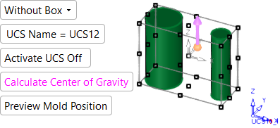
The following parameters are displayed.
-
Select the Preview Mold Position parameter, if needed, to update the position of the part in relationship to the mold and mold center based on the modified Work CS.
Parameters
|
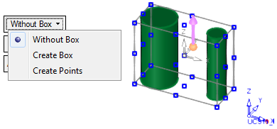
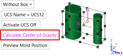
Without Box |
This is a dropdown list containing the following options:
|
The following parameters are also displayed.
UCS Name |
The name of the UCS being created. Click this parameter to edit the name. |
Activate UCS Off |
This
is a toggle option Activate
UCS On / Off, which enables you to activate (or not) the UCS
being created. Note: In NC operations, the default is set in the NC UCS Preferences (in the Activate Created UCS parameter). |
|
Calculate Center of Gravity |
Select this parameter to calculate the center of gravity for all selected objects.
|
||||
|
Preview Mold Position |
Use this option to update and preview the position of the part in relationship to the mold and mold center based on the modified Work CS. |
Notes:
-
If a UCS is selected, its origin is used as the origin point of the Work CS.
-
If delta parameters are defined (optional step), they are applied from the relevant point.
-
The orientations of the Work CS and bounding box change according to the directions of the selected UCS.
-
-
The center of gravity and the position of the UCS are not updated after geometric changes.
-
To re-calculate the center of gravity after geometric changes, press the Calculate Center of Gravity button again. If the Work CS was positioned on the center of gravity point and the point moves as a result of the re-calculation, the Work CS also moves to the new point (the new center of gravity).
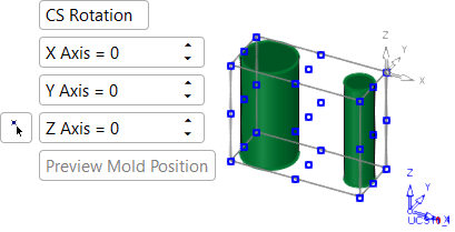
Optional Step 1  – UCS Rotation
-
Rotate the UCS by entering the X, Y, and Z rotation values. The UCS is re-orientated accordingly.
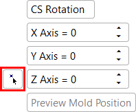
-
If needed, define a new X direction by selecting
 next to the Z Axis screen parameter and selecting two points on the part to create the new X-axis for the Work CS.
Note: When selecting two points to create the new X-axis for the Work CS, the order of point selection sets the new X vector. For example, picking left to right or right to left will generate different results.
Optional Step 2  – Delta from Pick Point
-
Set the X, Y, and Z delta offset values. The UCS is moved accordingly.
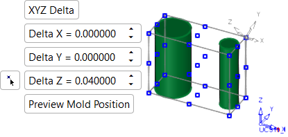
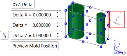
-
If needed, pick a Z reference point by selecting
next to the Delta Z screen parameter and selecting a point on the part. Additional delta values will be applied from the newly select point.

-
If the Work CS creation is complete, press OK
 or Apply
  in the Feature Guide.
When completed, the Work CS<number> feature will appear in the Feature Tree.


|