Line 
Access: Invoke the Sketcher, define the sketch plane and then invoke this function from one of the following locations:
-
Click the Line button
 in the Sketcher toolbar.
 -
Right-click the graphics area and select Line from the popup menu.
Create a line.
The line can be created in Free Mode or Dimension Mode. Toggle the Free / Dimension button as required.
Sketch Free/Dimension Note: You can toggle between Free and Dimension for circles, lines, ellipses, polygons and rectangles, so you can either create these entities without any dimension constraints, or to give preset dimensions on the geometry (which enables you to preview the exact shape before creating the entity).
Pre-dimensioned circles, ellipses, polygons and rectangles also have a center point, which makes it very easy to dimension or reference to the center of the geometry. Additional shapes can be constrained to the first one, or created with their own independent dimensions.
|
Free Mode: |
Dimension Mode: |
|
|
|
2D lines can be created with the following types of constraints:
|
This is the default Line option.
|
|
|
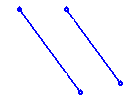
The two lines are mutually constrained.
|
|
|
Normal to an existing line. The two lines are mutually constrained.
|
|
|
Tangent to a circle or arc. The two entities are mutually constrained.
|
Dynamic constraint lines appear in the graphics display area to help you position your line relative to the XY axis or other entities, or snapped to points. When creating normal, parallel, or tangent lines you can use alignment constraints. See Alignment with Existing Entities.
When you create a new line relative to an existing entity, the two entities are mutually constrained. You can also define additional constraints for a new line.
Note: After a line has been placed, the system is ready to create a new line in its default option (Pt). The last point that you created is the starting point of the new line. To select a new starting point, first press exitexit.
Free Mode
Draw a line without any dimension constraints (default option). The line is extended to the point you pick in the graphics area.

Create a line using Free Mode
-
InvokeInvoke the Line Sketcher tool.
The cursor appears in the graphics display area as a crosshair-and-line .
. -
Pick a point that will be the start point of the line.
Note: If the first point is on a part of the reference entity, it is used as reference only and not the line endpoint. Pick another point to use as the line endpoint.
-
Pick the end point of the line. The line is created.
Dimension Mode
Draw a line with predefined dimension constraints.
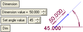
Set the parameters.
|
Dimension |
Toggle the Free / Dimension button as required. See the explanations above. |
||||
|
Dimension Value |
Set the length of the line. |
||||
|
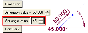
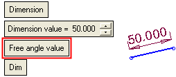
Set Angle Value |
This is a toggle option: Set Angle Value / Free Angle Value. This option enables you to create a line at a defined angle or to create a line at any angle.
|
||||
|
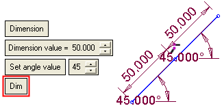
Dim |
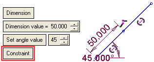
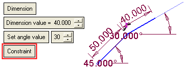
This is a toggle option: Dim / Constraint. This option enables you to either display the dimensions (length and angle) with every line created, or to display a dimension constraint on identically sized and angled lines.
|
Note: When working in Dimension mode, the last parameter values selected in the function are kept as the default for the next time you access the function.
Create a line using Dimension Mode
-
InvokeInvoke the Line Sketcher tool.
The cursor appears in the graphics display area as a crosshair-and-line .
. -
Set the required parameters. The preview automatically displays the size of the intended line as part of the mouse cursor.
Note: If the first point is on a part of the reference entity, it is used as reference only and not the line endpoint. Pick another point to use as the line endpoint.
-
Pick a point to position the line. The line is created according to the parameter settings (If the Free Angle Value option is used, a second click defines the angle of the line).


