|
|
3D Trajectory  : Options and Results
Access: Open this function from one of the following locations:
-
Select Electrode > Tools > 3D Trajectory from the menu bar.
-
Right-click the appropriate
 Location in the Electrode
Tree to display the popup
menu and then select 3D Trajectory
to display Step 2 of the function.
 -
Select 3D Trajectory from the Electrode Guide.
Define a 3D trajectory for an electrode. Use the Electrodes Simulation to simulate the electrode movement along this trajectory.
Note: This function is only available when the assembly is active.
Required Step 1 
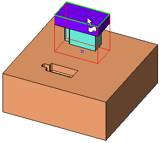
Pick the electrode whose trajectory is to be defined.
Required Step 2 
Define the trajectory steps for the electrode. This trajectory is composed of steps of either linear movement or rotation around the electrode axis.
The picked electrode is highlighted, the 3D Trajectory Manager appears and the following parameters are displayed:
|
Linear Movement and Rotation are toggle parameters |
|
|
|
|
|
Linear Movement / Rotation |
Toggle between Linear Movement and Rotation. |
|
Delta |
Set the delta distance of the current (Linear Movement) trajectory step. This distance can also be set by clicking on the arrow head or shaft and dragging the electrode to the required distance (you can drag in the arrow direction only). |
|
Z Axis |
Set the rotation angle of the current (Rotation) trajectory step. |
|
Reset |
Reset the movement to Delta = 0 or Angle = 0 degrees. The OK option is disabled. |
|
OK |
Accept the defined trajectory step. The trajectory step data is entered into the 3D Trajectory Manager. This option is available only if movement (Linear or Rotation) has been defined. |
Linear Movement
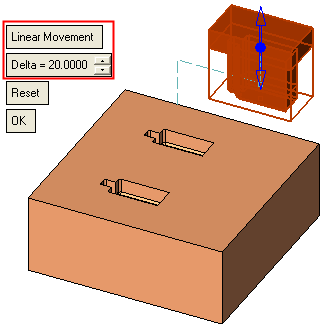
Set a linear trajectory step(s) for the electrode. This is the default trajectory option and displays a directional arrow.
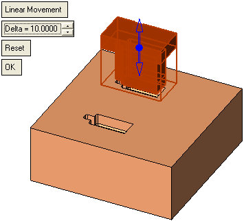
Set a linear trajectory
-
Set the direction using the arrow. Click on the arrow origin to open the direction menu. The default direction is the +Z of the electrode.
-
Set the delta distance of the current trajectory step.
-
Press OK to accept the defined trajectory step. The trajectory step data is entered into the 3D Trajectory Manager.
Rotation
Set a rotation trajectory step(s) for the electrode.
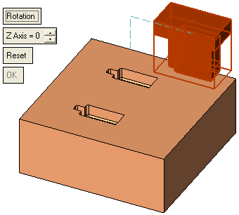
Set a rotation trajectory
-
Set the rotation angle. The rotation axis is around the Z axis of the electrode UCS.
-
Press OK to accept the defined trajectory step. The trajectory step data is entered into the 3D Trajectory Manager.
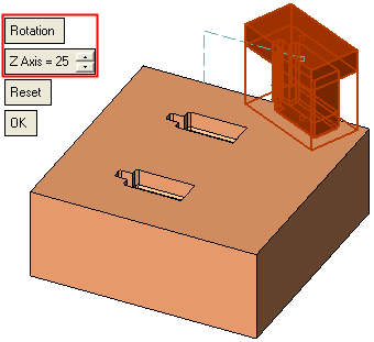
To edit the defined trajectory, use the 3D Trajectory Manager.
Click OKOK or ApplyApply in the Feature Guide to complete the function. Once the trajectory has been defined and the function exited, the following occur:
-
The defined trajectory is displayeddisplayed.
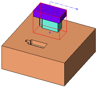
Linear Movement steps are displayed using a dashed line.
Rotation steps are displayed by small points.
-
Additional options become available in the Location popup submenupopup submenu:
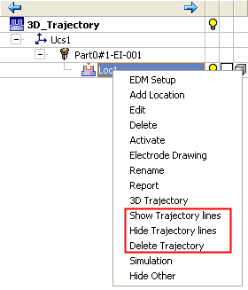
These options enable you to Show or Hide the trajectory lines, or to Delete the trajectory.
-
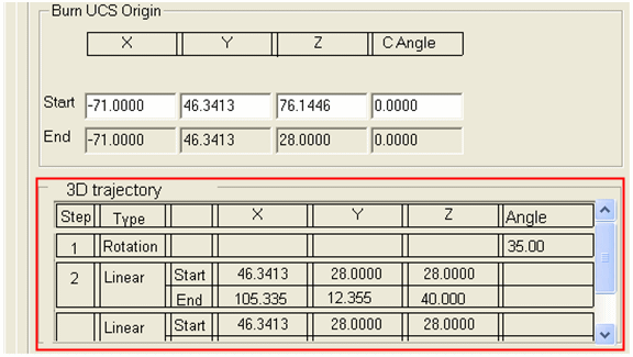
The trajectory points and parameters are displayed in the EDM Setup for Standard machines. They appear in the report of the specific Location as followsfollows:
-
The trajectory points and parameters are displayed in the EDM Setup Output File as followsfollows:
[COMPONENT]
NAME = Part for copy Electrode-EL
FILE_NAME =
MATERIAL = Aluminium
UNITS = MM
NOTE =
[ELECTRODE_0001:01]
NAME = Part for copy Electrode-EL-001:Loc1
FILE_NAME =
UNITS = MM
COMMENT =
BLANK_TYPE = Rectangular
BLANK_ORIGIN_X = 0.0000
BLANK_ORIGIN_Y = 62.4995
BLANK_ORIGIN_Z = 45.0000
BLANK_HEIGHT = 41.6127
...
[TRAJECTORY]
STEP_1_ANGLE =30
STEP_2_LINEAR_START=3.3, 78, 56.78
STEP_2_LINEAR_END= 99.6, 77, 66
BURN_UCS_ROTATION = 0.0000
QUANT_RO = 4
ORBIT_TYPE_RO = 3-D ORBITING
ORBIT_VALUE_RO = 0.0021
SPARK_GAP_RO = 0.0001
ORBIT_OFFSET_RO = 0.0022
MATERIAL_RO =
QUANT_PF = 3
ORBIT_TYPE_PF = 3-D ORBITING
ORBIT_VALUE_PF = 0.0000
...
-
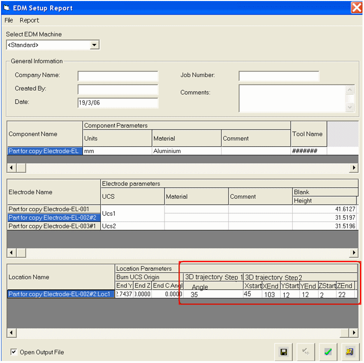
The trajectory points and parameters are displayed in the EDM Setup Report as followsfollows:
|


