Automatic Coloring  : Options and Results

Access: Open this function from one of the following locations:
-
Select Analysis > Tools > Automatic Coloring from the menu bar.
-
Select Automatic Coloring from the Electrode Guide Toolbar.
To display these options, activate an electrode.
Assign colors and sets to faces based on their direction, position and function. For example, for electrodes, single-color sets will be created for the burning area, extension and base.
For the electrode designer, the single-color sets validate the electrode design. For the electrode manufacturer, they enable the automatic and clear selection of the appropriate geometry to be used in NC Templates.
Required Step 1 
Pick objects (and wires) to undergo analysis and <exit><exit>.
|
Objects picked: |
|
|
|
|
Required Step 2 
Set the parameters and start the analysis. The following parameters are displayed:
A directional arrow is displayed. The default direction in an electrode file is towards the burn faces. The default direction in a non-electrode file is the +Z of the active UCS.
|
Analyze All Faces |
This is a toggle option, Analyze All Faces / Ignore Assigned Faces that enables you to controls which of the selected faces is included in the analysis.
If there are no sets with the same names or all the sets are empty, this parameter is grayed out on Analyze All Faces. |
||||
|
Settings |
Display the Automatic Coloring Settings dialog; see below. |
||||
|
Start Analysis |
Perform the analysis based on the current parameter settings. The system applies different colors to the different faces. |
Automatic Coloring Settings Dialog
The Automatic Coloring Settings dialog is displayed when the Settings parameter is selected.
|
|
This dialog shows the available geometry type sets (and colors). The system analyzes the selected geometry according to the categories displayed in this table, and attaches faces to an appropriate set (and color).
You may also create a 'user-defined geometry' set to which you may later add faces manually.
See Usage Examples of this dialog and also in the Mark Burn Faces According to Analysis explanation, below.
For each type of face (row in the dialog), the following parameters are available:
|
Create Set |
The checkbox defines whether or not to create a specific set type. If the checkbox is selected, a set By Criteria is created containing the defined criteria (see Analysis Results below). |
|
Set Name |
This field displays the available 'automatic recognition' geometry types. If the type of geometry exists in the selected body, it will be recognized by the system while analyzing the electrode. The names describe the geometry shape and functionality, and therefore will be helpful for later use when applying NC templates. The sets can be renamed. If 2 or more names are identical, the color of the first duplicated row is displayed; the colors of the other duplicated rows are grayed out (they will have the same color when the set is created).
Note: Top Chamfer set faces.
|
|
<Color> |
Define the face color for each set. |
|
From Angle - To Angle |
Set a limit angle for some of the sets type. This means that only faces of the relevant type, with a slope within the defined angle range, will be recognized as part of the set during the analysis. |
The following options also appear in the Automatic Coloring Settings dialog:
|
Don't Create Empty Sets |
The checkbox defines whether or not to create a specific set type. If the checkbox is selected, sets which do not include any geometry will not be created. |
|
Mark Burn Faces According to Analysis |
The checkbox defines whether or not to mark faces according to the analysis results. If the checkbox is selected, the following occurs when you press OK in the Feature Guide for this function:
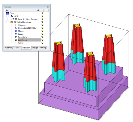
By default, this checkbox is turned OFF. In many cases, electrode components (i.e. burning surfaces, extensions) can be designed without using the Electrode environment's automatic tools (usually when the electrode is designed in solid). However, in such cases, the components are not recognized as such by the system (they do not have electrode attributes) and, therefore, their visibility cannot be controlled from the Electrode Tree (which provides centralized control for hiding/showing the blanks, holders, burn faces and extensions for electrodes). The Mark Burn Faces According to Analysis option enables you to mark the components so they can be recognized by the Electrode Tree for centralized visibility control. In the example below, the electrode was designed using solid operations, and the burning faces were not extracted using the Electrode application. Nevertheless, after running the Automatic Coloring function they are recognized as burning faces (burning face attributes are attached to them) and their visibility can be controlled by the Electrode Tree.
|
The following buttons appear in the Automatic Coloring Settings dialog:
|
|
Save as Default: Save the current settings as the default. These default settings will be used whenever this operation is re-invoked. New analyses will use the saved defaults. |
|
|
Reset: Reset all values and settings to the system defaults. |
|
|
OK: Accept the changes, perform the operation, and close the current dialog/task. |
|
|
Cancel: Cancel all changes and close the dialog/task without saving the settings. |
Analysis Results
When the analysis is completed, the following occurs:
The object selected in required step 1 is displayed in the defined colors.
Example:Example:
|
Object before analysis: |
Object after analysis: |
|
|
|
|
|
A new set By Criteria is created for each checked row in the Automatic Coloring Settings dialog which does not already have a predefined set of the same name.
Example:Example:
|
Sets before the analysis: |
Sets after the analysis: |
|
|
|
The set includes the defined color and the "Face" Entity Type. The set excludes the Holder Set Name as defined in the Electrode Preferences.
Example:Example:
If a set By Criteria is defined and a set of the same name already exists, the predefined set remains unchanged.
If a row in the Automatic Coloring Settings dialog is unchecked, the faces that were analyzed as belonging to it will be put into the first checked set the system finds, that has the same color.
If such a set cannot be found, then the related set (and color change) is ignored. The related faces found in the analysis will not go into the unassigned set.
Press OK ![]() in the Feature Guide to complete the function.
in the Feature Guide to complete the function.
Usage Examples
Simplifying Colors
The Automatic Coloring function includes many sub-types. In some cases (usually complex electrodes), you may want to combine all the sub-types into one group for ease of reference; this can be done using the Automatic Coloring function. See the examples below.
|
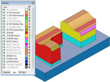
The electrode below is colored using the standard color scheme. The large amount of color variations allows you to adapt a dedicated machining technology for each color. |
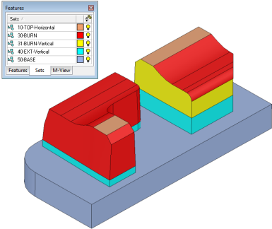
The electrode is colored using a simplified color scheme. Most of the burning surfaces are colored in red and only the top horizontal faces and the vertical burning faces have a different color. |
|
|
|
Used-Defined Sets
Some sets may need to be user-defined as they are not part of the standard automatic coloring function. See the examples below.
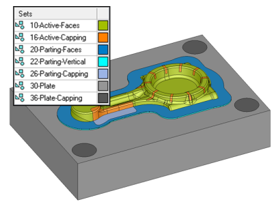
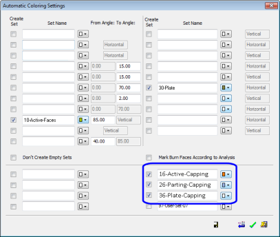
| A part is colored with a few colors. The capping faces belong to sets (16, 26 and 36) that are not part of the standard automatic coloring function. | The Automatic Coloring Settings dialog showing the three additional sets for the capping. |
|
|
|