|
|
Blank on Binder  : Options and Results
Access: Open this function from one of the following locations:
-
Select Die Design > Geometry Manipulation > Blank on Binder from the menu bar.
-
Select Geometry Manipulation > Blank on Binder from the following Die Design Guide: Die Process Design Guide (Forming).
Blank a set of adjacent stitched and skinned faces on the extension of other sets of faces, using finite element analysis (FEA).
This function uses a finite element enginefinite element engine for blanking (flanging) a given set of adjacent stitched skinned faces and then create a contour on another set of faces, based on the material properties and thickness.
The Finite Element Analysis (FEA) engine used in the DieDesign application is based on technology supplied by the Forming Technologies Inc (FTI) 3rd party engine. For additional information on FTI, see www.forming.com.
The finite element engine is used in the following functions:
Whenever the finite element engine is used, resultant forces are calculated and stored for usage in the Die Forces operation.
Force Calculation: The force calculation employed depends on the type of operation being calculated. For additional information and to define some of the values used in force calculations, see the Die Force Calculation Preferences.
Correction Factor: A Die Preference option enables the setting of a default Correction Factor to manipulate forces calculated by the finite element engine. The forces displayed in the above mentioned functions will be multiplied by this factor.
Various types of Blank on Binder options exist,
Note: The binder object may contain any type of faces but for best results it is recommended that the binder object contains only smooth, planar and cylindrical faces.
Local Blank on Binder
Before activating the Blank on Binder operation, perform the following steps:
-
Skin the Faces.
The first step that is required when creating a Local Blank on Binder is to skin the object containing the required faces. See the Die Skin function for addition information. -
Create the Extended (Binder) Faces
After Die Skin has been performed, the next step is to create the extended binder faces. This includes:-
Unstitch the Faces.
This step describes how to Unstitch the required faces (on which to create the binder), as described in the following procedure. See the Unstitch function for additional information.
In the example below, the yellow faces are unstitched: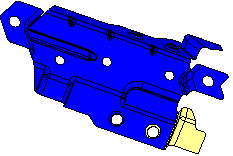
-
Create a Composite Curve.
This step describes how to create a composite curve which is an extension of the selected faces. See the Composite function for additional information.
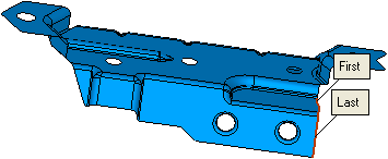
In the examples below, the entities for the composite curve are selected and the yellow faces are hidden: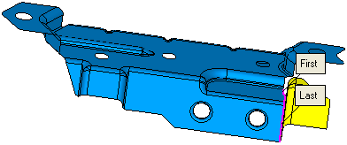
-
Create the extended binder faces.
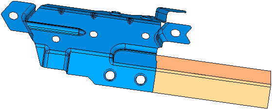
See the Extend function for additional information. In the example below, the extended binder faces are created.
-
-
After Composite and Extend have been performed, the next step is to stitch all the extended faces. See the Stitch function for additional information.
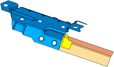
In the example below, the extended faces were selected and the yellow faces were shown (Show ):
):
|

