|
|
Burn Body : Options and Results


Access: Open this function from one of the following locations:
-
Select Electrode > Geometry > Burn Body from the menu bar.
-
Select Burn Body from the Electrode Guide.
Create a solid body from the burning faces. When creating electrodes, after the usual extract of the faces to be burned, the Burn Body function automatically surrounds and trims the burn surfaces into a closed solid object.
Note: This function is only available when an electrode is active in an Assembly environment.
The function has several extension options that can be adjusted to provide cavity clearance. The Burn Body and Solid Extension functions enable you to create a body and extend it all the way up to the electrode base. Together, these functions can be used to create electrodes using solid tools.
Required Step 1 
Pick the burning faces around which the body (or bodies) will be formed.
By default, the system automatically selects all the burning faces of the electrode that do not have a body on them and jumps to the next stage. However, you can return to this stage and change the selection. If no burning faces are found automatically, the system remains in this step until the burning faces are manually selected.
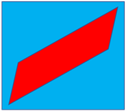
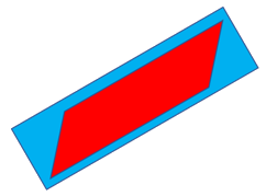
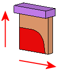
The burning faces (in RED) are automatically selected, and a body around each lump is displayed.
|
|
|

If the burning faces are manually selected, click exitexit to continue to the next step.
The examples above show a multi-lump (multiple burn area) electrode (by proximity, faces that touch each other are considered to be in the same lump). The burning faces for each lump are automatically selected and a box around each lump is created along the directions of the electrode extraction or blank if it exists. The box is previewed with default or last used offsets (see the next stage).
Required Step 2 
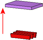
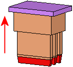
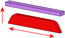
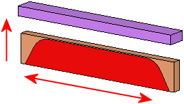
Define the way the body (or bodies) will be built around the faces. The direction arrow is displayed to define the extension direction.
A box around each lump (of burning faces) is created along the directions of the electrode extraction or blank if it exists. The box is previewed with default or last used offsets. Set the screen parameters as required.
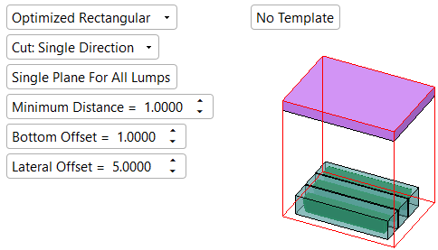
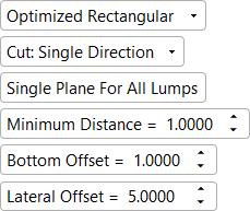
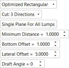
The following parameter options are available.
|
|
|
|
|
|
|
Press OK ![]() or Apply
or Apply ![]() in the Feature Guide to complete the function.
in the Feature Guide to complete the function.
When completed, the Burn Body feature will appear in the Feature Tree.
Parameters
|
Optimized Rectangular / |
When creating a Burn Body, Cimatron first creates a solid box around the extracted burning faces. This box can be created as Optimized Rectangular (the default option) or Rectangular.
|
||||||||||||||
|
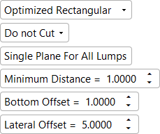
Cut: Single Direction / |
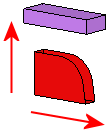
Set the electrode type from the dropdown list of the options (for each type, the extension direction(s) are automatically recognized).
|
||||||||||||||
|
Single Plane for All Lumps / |
Toggle option that enables you to position the lumps on single or multiple planes. This option is displayed only if more than one lump is detected. The default value is set in Preferences, however, the last used value for this parameter is always displayed.
|
||||||||||||||
|
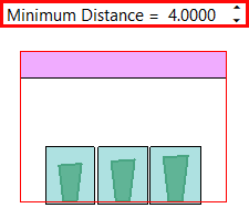
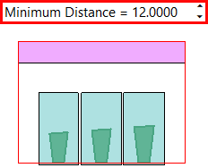
Minimum Distance |
Set the minimum distance of the top face(s) of the solid body (or bodies) from the highest point on the lump(s) towards the electrode base. The actual distance will depend on the toggle Single Plane for All Lumps / Multiple Planes option selected. The default value is set in Preferences, however, the last used value for this parameter is always displayed.
|
||||||||||||||
|
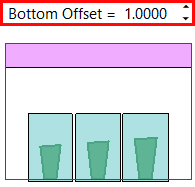
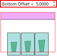
Bottom Offset |
Set a bottom offset to the burn body or bodies. The default value is set in Preferences, however, the last used value for this parameter is always displayed.
|
||||||||||||||
|
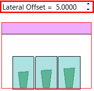
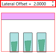
Lateral Offset |
Set a lateral offset to the burn body or bodies. The default value is set in Preferences, however, the last used value for this parameter is always displayed.
|
||||||||||||||
|
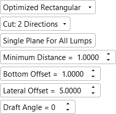
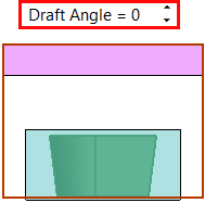
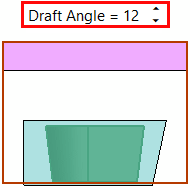
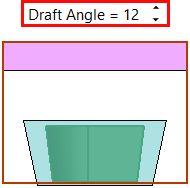
Draft Angle |
Add a draft angle to the solid body (bodies). This parameter is displayed if either the 2 Directions or 3 Directions option is selected above. The default value is 0.
|
||||||||||||||
|
Apply Template / |
Toggle option that enables you to apply a predefined electrode template to the electrode while it is being created. Apply Template is the default setting. |


|