|
|
Compare  : Options and Results

Access: Use this function from the following location:
-
Select Tools > Geometry > Compare from the menu bar.
Compare and detect changes between the active part (original) and a selected (reference) part.
Before usingusing the Compare function, load the first of the part files to be compared (the original part). For example:
Required Step 1 ![]()
The Cimatron Explorer is displayed. Select another part file (the reference part) to be compared with the previously loaded part file.
Once the second part file is loaded, you are prompted to either accept the current screen location of the parts to be compared (by default they are positioned according to the same UCS - the reference part is positioned on the original part) or to re-locate them by picking different UCSs.
In this example, the following parts have been selected. Notice that they look very similar, without any recognizable differences as shown below:
|
First part to be compared - loaded before invoking the Compare function: |
Second part to be compared - loaded as the first operation in the Compare function: |
|
|
|
As mentioned above, after loading the second part file, the result can be viewed in two ways:
| Either: Press <exit><exit> to accept the current location. In this case, the reference part is positioned on the original part as shown below. (In this example, notice the difference between the two part files - some of the entities have been changed). | Or: Pick different UCSs and then press <exit><exit>. In this case, each part is positioned according to its own UCS as shown below. |
 |
 |
In both the methods, when you press <exit><exit> the system takes you to Required Step 2 and displays the Compare parameters.
Required Step 2 
The screen location of the original and reference faces depends on your previous selection.
|
The default positioning was accepted - the parts are positioned according to the same UCS - the reference part is positioned on the original part: |
Different UCSs were selected to position the parts - each part is positioned according to own UCS: |
|
|
|
Whatever the screen locations of the parts, the parameters that are displayed for this step are as follows (see the parameter descriptions below):
  |
Note: Depending on the screen location of the parts, some of the face "types" may not be immediately identified. For example, as can be seen in the images above, the added and removed faces are immediately identified when the parts are positioned according to different UCSs. Similarly, the coincident faces are immediately identified when the parts are positioned according to the same UCS. Use the hide/show toggle buttons to display the appropriate faces.
|
Distance Tol. |
Set the distance tolerance. This is the minimum distance between the end points of all edges between two compared faces. If the distance is less than the specified tolerance value, then the compared faces are regarded as identical. |
||||||||
|
Publish to PDF |
Publish to PDF to create 3D PDF files that include parts and assemblies from Cimatron. When the Publish to PDF button is selected, the Publish to PDF dialog is displayed giving you additional controls before the selected entities are exported to PDF. One of these controls enables you to define the output file name. When the Publish to PDF option is invoked from this Compare function, the default name of the output PDF file is composed of the following: <Current_File>-<Compared_File>.PDF The PDF report is titled Compare Report, and below the visual area the names of the First and Second Parts are displayed. |
||||||||
|
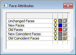
Face Attributes dialog |
The Face Attributes dialog enables you to control the following face attributes to improve clarity:
The display shows new geometry in blue, and geometry to be removed in red. In addition, Coincident faces are also highlighted. Coincident faces are two or more faces that occupy the same space and represent the same surface. These are faces that didn’t actually move in the new revision but do have a new trimmed boundary. They are found in the area surrounding a change, and being able to set them apart in a different color makes the actual changes more distinct and easier to spot. A similar dialog also appears in the ECO Comparison function. |


Note: In some cases, the default settings of the Compare parameters may result in the following message being displayed before the parameters are displayed:
In these cases, press OK to display the parameters.
This message may also appear after changing the tolerance parameter, Distance Tol.
Optional Step 1 
Pick unique reference (new) part faces that will not be added to the original (old) part. This option is displayed once the analysis is complete.
Pick the face(s) and then press <exit><exit>. In this step, the following parameters are displayed:
|
|
|

|
Reset |
Reset the compare results (undo the changes made in this Optional Step). |
|
Face Attributes dialog |
For explanations of the Face Attribute dialog, see the Parameter descriptions above. |
Notes: To complete the pick operation, press the MMB to exit after selecting the face(s).
-
An Unchanged Face turns red and will be removed.
-
A New Face or New Coincident Face is hidden and will not be added.
-
An Old Face or Old Coincident Face turns gray and will not be removed.
Optional Step 2 
Invoke the Deviation Map function to calculate the distances between the compared parts. This option is displayed once the analysis is complete.
When the Deviation Map function is invoked from the Compare function, the following occurs to calculate the distances:
The first step of the deviation mapping (setting the original object/faces) is automatically defined as follows:
New Faces + New Coincident Faces.
(This data is available once the Compare analysis is complete - see the Face Attributes dialog shown above).
The second step of the deviation mapping (setting the target object/faces) is automatically defined as follows:
Old Faces + Old Coincident Faces.
(This data is available once the Compare analysis is complete - see the Face Attributes dialog shown above).
The deviation distance tolerance value is set to the default +- 0.05.
The Deviation Map function is displayed at the third required step, ready to run the deviation analysis.
Press OK ![]() or Apply
or Apply ![]() in the Compare Feature Guide.
in the Compare Feature Guide.
When completed, the Compare feature will appear in the Feature Tree:

|