|
|
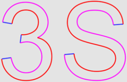
Composite Curve  : Options Results
![]()
![]()

Access: Open this function from one of the following locations:
-
Click
in the toolbar. -
Select Wireframe > Main Tools > Composite Curve from the menu bar.
-
Select Composite Curve on the popup menu if no geometry is selected or if one or faces are selected.
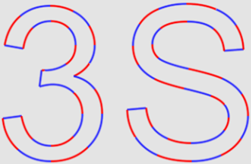
Create a contour from a series of curves/edges.
Create a single 2D or 3D curve by joining two or more curves (lines, edges, splines, etc.). Composite curves can be open or closed, have sharp or rounded corners, and be approximated into Nurbs splines.
Required Step 1 
-
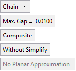
Set the parameters and pick curves (edges, lines, splines, sketches, etc.). The following parameters are displayed.
|
|
|
|
|

|
|
||||||||||||||||||||||||||||||||||||||||||||||||||||||||||||
|
|
|
||||||||||||||||||||||||||||||||||||||||||||||||||||||||||||
Parameters
|
|||||||||||||||||||||||||||||||||||||||||||||||||||||||||||||

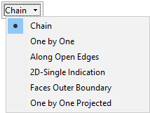
The following examples demonstrate the use of each of the picking options.
- Chain
- One by One
- Along Open Edges
- 2D-Single Indication
- Faces Outer Boundary
- One by One Projected
-
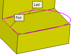
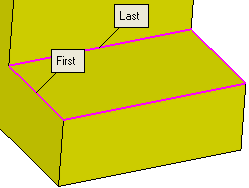
Chain
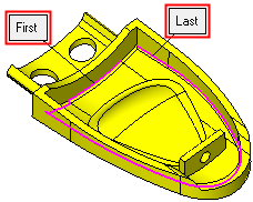
Create a contour by picking a curve, a direction, and then the last curve in the chain. The shortest possible chain connecting the two curves will be selected to create the contour.
Using the Chain option, pick the First curve and Last curve.
A composite curve is plotted along the most logical course.
Again pick a "Last Curve" to complete the composite curve.
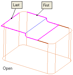
If you need to create a composite curve on half of the top outer edge of the geometry, you can pick the First Curve and Last Curve adjacent to each other.
In this example, the composite curve required is the logical path from the First Curve to the Last Curve.
Toggle to the Spline option if you wish to create a single spline along the edges.
-
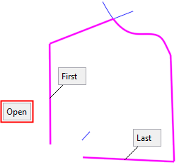
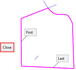
One by One
Create a contour by picking individual curves.
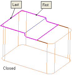
If you need to plot a path with individual curves to form the composite curve, use the One by One option combined with the Chain option. The Open/Close toggle parameter lets you close the composite curve automatically or leave it open.
-
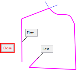
Along Open Edges
Create a contour by picking a curve and then picking another curve adjacent to it. The path of the created contour is along open edges.
If you use the Along Open Edges option, picking the same First Curve and Last Curve will plot the composite curve and include open edges.
-
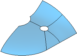
Faces Outer Boundary
Create a contour by picking a face. The outer boundary of the picked face is selected as a closed contour. If you choose two or more adjoining faces, the contour that defines the outer boundary of all faces will be selected.
Use the Faces Outer Boundary to plot the curve along the outer boundary of the geometry. In this example the box selection is used to select the whole geometry.
In the following example, a series of faces are picked: The composite curve formed along the outer boundary of the picked faces.
The composite curve formed along the outer boundary of the picked faces.
Click OKOK![]() or ApplyApply
or ApplyApply![]() in the Feature Guide to complete the function.
in the Feature Guide to complete the function.
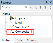
The Composite feature will appear in the Feature Tree.


|