|
|
Cutters & Holders Parameters  : Cutter Tab – Cutter Area
![]()
![]()
Access: Open this function from one of the following locations:
The Cutters and Holders dialog (or the minimized version - the Select Only Mode):
-
When not editing or creating a procedure, select NC-Process > Cutters > Cutters from the menu bar or select Cutters
in the NC Guide Toolbar. -
While editing or creating a procedure, use one of the following methods (in both methods, the Select Only Mode is displayed):
-
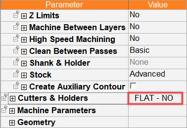
In the Advanced Mode, click on the cutter name in the Procedure Parameter Table.
-
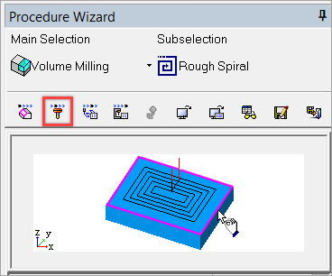
In the Wizard Mode, select the cutter button.
-
-
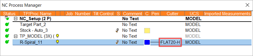
In the Process Manager, click on the cutter name in the procedure row (in this case, the Select Only Mode is displayed).
This topic discusses how to set the parameters in the Cutter Technology and Tip pane. After the cutter has been selected (Technology and Tip/Type), the cutter-specific geometry parameters are displayed.
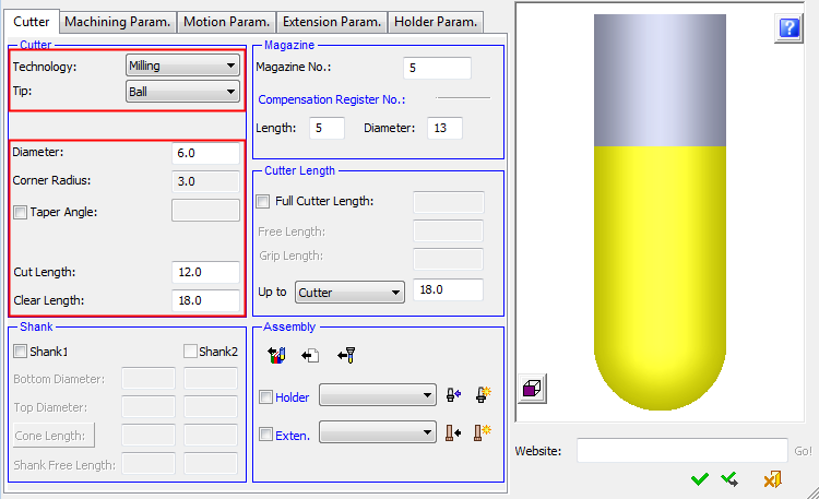
When setting the cutter parameters, first define the type of cutter you require by selecting from the available options in Technology section of the Cutter tab.
The Technology and Tip/Type options that you select define the types of parameters that are displayed in this tab (see Cutter Geometry for a graphical representation of the different cutter types and the various cutter parameters).
The cutter definition process is as follows:
-
Select the Cutter Technology.
-
Select the Cutter Tip or Type (dependent on the cutter technology).
-
Set the cutter-specific parameters.
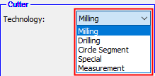
Cutter Technology
Set the machining Technology type. The options are displayed in a dropdown list:
- Milling
- Drilling
- Circle Segment
- Special
- Measurement (Probe)
- See also Special Shaped Cutters.
|
Technology types |
In the case of a drill tool, the dropdown list is dimmed with the Drilling option displayed. |
|
|
|
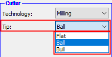
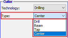
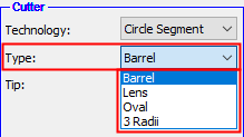
Cutter Tip/Type
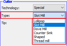
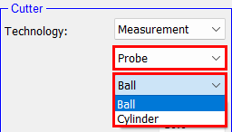
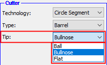
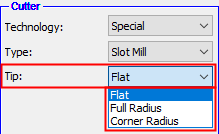
When the machining Technology type has been defined, set the specific cutter type from within the Technology range.
|
Milling cutter tip types |
Drilling cutter types |
Circle Segment cutter types |
Special cutter types |
|
|
|
|
|
|
Measurement probes |
Select the required tip. |
Select the required tip. |
|
|
|
|
|
When the Technology and Tip/Type are selected, this automatically updates:
-
The parameters displayed in the Cutters and Holders dialog.
-
The display of the cutter in the Cutters and Holders dialog (Cutter Preview Pane).
Notes:
-
See Special Shaped Cutters for information regarding why these kinds of cutters are sometimes required and how to create them.
-
Barrel type is a general name for a family of cutters that have variable radii along their profile. In roughing and finishing strategies, the large curvature of these cutters allows the use of a larger step over, yet keeps the same surface quality. The following procedures support Barrel, Lens, and Oval cutters:
-
The following 2.5-Axis procedures (on which the cutter is considered as a flat end mill tool):
-
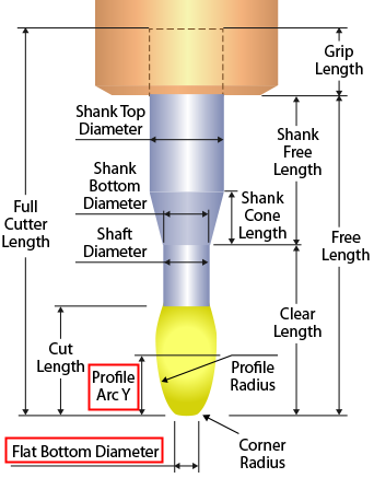
For Barrel Bull Nose cutters, at least one of the following parameters needs to be defined in order to create the cutter: Flat Bottom Diameter or Profile Arc Y. If these parameters are not available in the manufacturer's catalog, contact the manufacturer's support for these parameters and request the DXF files or drawings.
-
Drilling tools can be used only with the Automated Drill procedure or the Legacy Drill procedure. Therefore, when invoking the cutter table from another procedure type, you cannot create a new drill tool.
-
A cutter that was already saved cannot be changed to Drill, and vice versa.
-
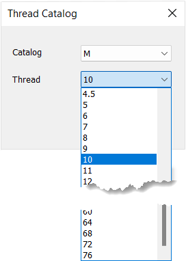
The Tap drilling tool enables you to define the type of thread. The thread type appears on a button in the parameter section of the Tap tool.
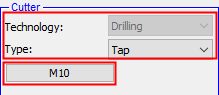
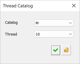
Press the button to display the Thread Catalog dialog.
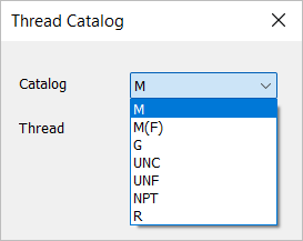
The following thread catalogs are supported.
The thread type is dependent upon the thread catalog type. Set the thread type as required.
Cutter-specific parameters
After the cutter has been selected (Technology and Tip/Type), the cutter-specific geometry parameters are displayed. Set these parameters as required.

Note: If the cutter is defined as a Special - Counter Sink, the parameters Diameter (C.S.) and Blind Diameter are displayed instead of the Diameter parameter. In this case, the Diameter column in the cutter table refers to the Blind Diameter. See the example imageSee the example image.
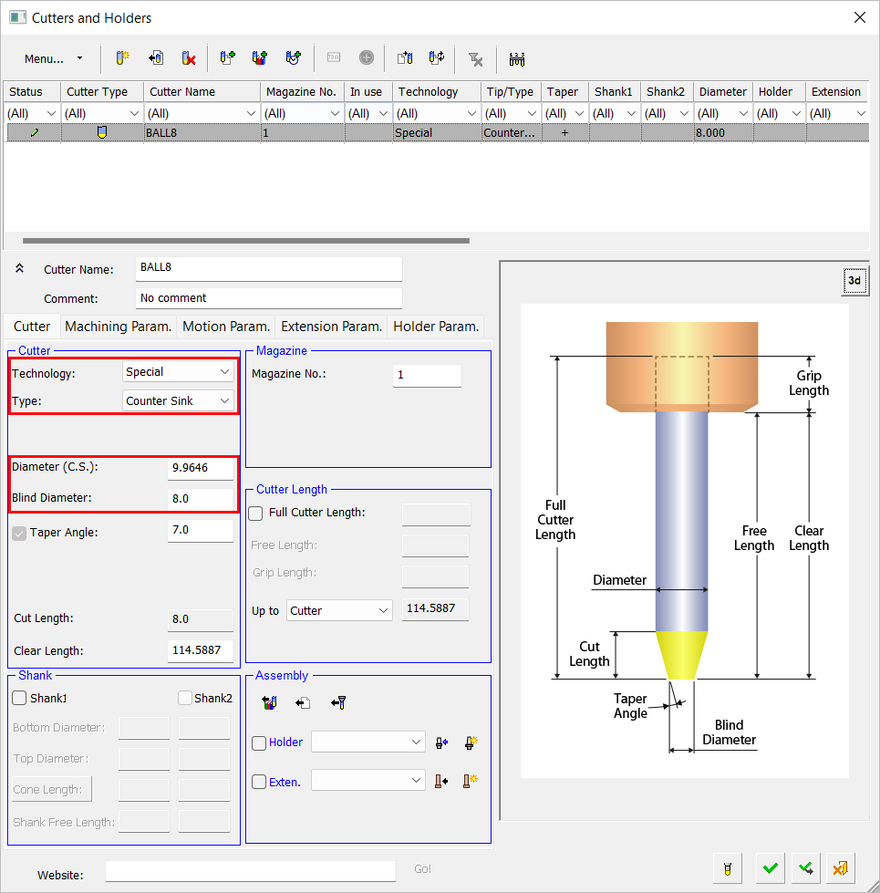
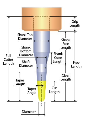
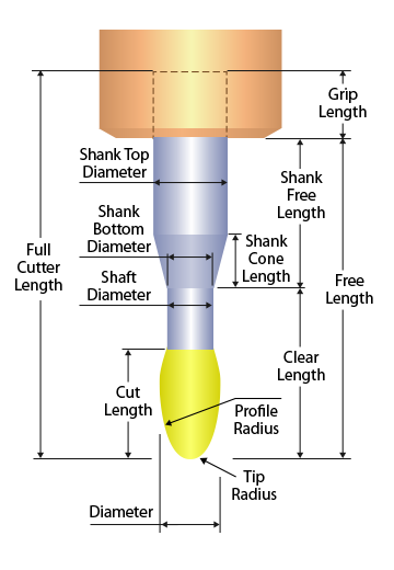
To visualize the parameters below, see the image on the right. See also Mills Best at Slope Angles Range below.
|
Diameter / |
Set the diameter of the cutter. |
Milling Ball 3 Radii Ball example3 Radii Ball example
Barrel Bull Nose
Barrel Ball
3 Radii Ball |
|
Corner Radius |
Set the corner radius of the cutter. |
|
|
Taper Angle |
When this checkbox is marked |
|
|
Taper Length / Shaft Diameter |
The Taper Length / Shaft Diameter toggle parameter button becomes available. These parameters are inter-related, a change in one affects the other. |
|
|
Cylinder Height |
Height of the cylinder Minimum setting = 0.001 This setting is only applicable to Measurement Probe Cylinder cutters and is only displayed in the dialog if Measurement Probe Cylinder is selected in the Technology area of the Cutter tab. |
|
|
Free Stylus Diameter |
A cylinder is added between the ball and the cone part of the shank. Its diameter is named Free Stylus Diameter and must be greater than 0 and less or equal to the tool diameter. Notes:
This setting is only applicable to Measurement Probe cutters and is only displayed in the dialog if Measurement Probe is selected in the Technology area of the Cutter tab. |
|
|
Tip Radius |
Set the cutter tip radius for Barrel cutters. To visualize this parameter, click the Barrel Ball example on the right. |
|
|
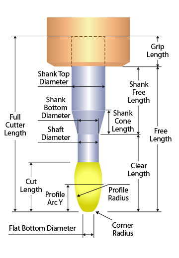
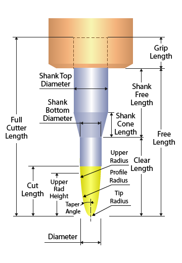
Profile Radius |
Set the cutter profile radius for 3 Radii and Barrel cutters. |
|
|
Upper Radius |
The upper radius of the curved part of the cutter. Displayed for 3 Radii cutters. |
|
|
Taper Angle/ |
A toggle option displayed for 3 Radii cutters. The Taper Angle is the line tangent to the Profile Radius and the cutter axis. The Upper Radius Height is the height of the point on which the curved part of the cutter ends. |
|
|
Flat Bottom Diameter/ |
A toggle option displayed for Barrel cutters. For Barrel Bull Nose cutters, at least one of the following parameters needs to be defined in order to create the cutter: Flat Bottom Diameter or Profile Arc Y. If these parameters are not available in the manufacturer's catalog, contact the manufacturer's support for these parameters and request the DXF files or drawings.
|
|
|
Cut Length |
Set the cut length of the cutter. |
|
|
Cut Length/ |
Set the relevant toggle parameter for Barrel cutters. To visualize this parameter, click the Barrel Bull Nose example on the right. |
|
|
Clear Length |
Set the clear length of the cutter. |

Notes:
-
The non-cutting portion of the cutter is considered as follows:
-
If conic (the Cut Length is shorter than the Taper Length), it is considered in all procedures that support a shank, as a Shank. However, this "Shank" is not "ignored" when the option Ignore Shank is selected. In other procedures, it is considered as a cutting portion of the cutter.
-
If cylindrical (the Cut Length is longer than or equal to the Taper Length), it is considered as a Shaft.
-
-
In all the situations that the cutter is shown (e.g., Cutter Table, Navigator, Simulator, etc.) the non-cutting portion of the cutter is displayed the same as the Shank portion of the cutter.
-
The Taper Length and Shaft Diameter are displayed in the Cutter Table.
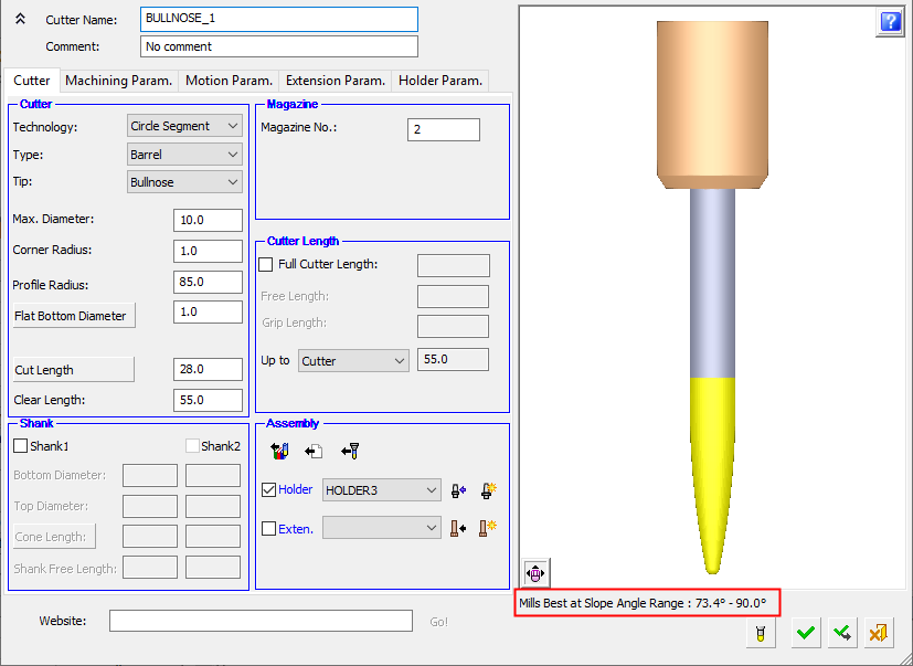
Mills Best at Slope Angles Range
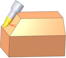
Circle Segment cutters mill best with the largest radii of the cutter tangent to the surface it mills.
For Circle Segment - Barrel cutters, the best slope angle range for milling is displayed for a specific cutter below the cutter image in the Cutters and Holders dialog. This angle range specifies the angle between the cutter axis and the normal of the face it mills and indicates the minimum and maximum slope angles of faces that can best be milled by a specific cutter.
|
|
|
|
The best slope angle range for milling is displayed for a specific cutter. |
|

These minimum and maximum slope angles may be used in relations using their respective short names: minslope and maxslope.
These slope angle ranges are currently only displayed for Barrel cutters. For all other cutter types, minslope = 0°, maxslope = 90°.
Note: A UCS can be created such that the tool axis is tangent at the appropriate angle to the face it mills.
|