|
|
ECO Comparison: Options and Results


Access: Open this function from one of the following locations:
-
To create a NEW comparison:
Right-click an ECO folder (for example ECO#1) in the ECO Tree and select New ECO Comparison. -
To EDIT an existing comparison:
Right-click an ECO comparison folder (under an ECO folder) in the ECO Tree and select Edit Comparison. -
To UPDATE an existing comparison:
Right-click an ECO comparison folder (under an ECO folder) in the ECO Tree and select Update Comparison.
There is no further interaction when running an update.
See the ECO Tree > popup menus for further information on the options.
Compare and detect any engineering changes made between the ECO part received from the customer and the part to be updated (the work part, which could be a previous ECO or a master part). These changes can then be edited, and the model consequently updated.
In a typical system development cycle, the specification or the implementation is likely to change during engineering development or during integration of the system elements. These last-minute design changes are commonly referred to as Engineering Change Orders (ECOs) and affect the functionality of a design after it has been wholly or partially completed.
Note: Default ECO comparison colors are defined in the Preferences. The colors set in the Preferences are given to any new comparison. Changes in the ECO dialog do not affect the Preferences.
Required Step 1 
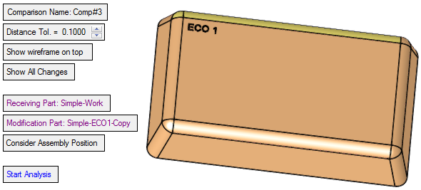
Enter the tolerance and/or select the display mode. The following parameters are displayed:
|
Comparison Name |
Set the name of the comparison node in the ECO Tree. The default name is Comp#<n>, where <n> is an index number that increases with every ECO Comparison operation. For example, Comp#1, Comp#2, etc. |
||||||||
|
Distance Tol. |
Set the distance tolerance. This is the minimum distance between the end points of all edges between two compared faces. If the distance is less than the specified tolerance value, then the compared faces are regarded as identical. |
||||||||
|
Show wireframe on top |
This is a toggle option, Show wireframe on top / Don't show wireframe on top.
|
||||||||
|
Show All Changes |
This is a toggle option, Show All Changes / Show Unapplied Changes Since Previous. For examples of the use of these parameters, see Mending Example.
|
||||||||
|
Receiving Part |
Pick the part that will receive the change; this is usually the work or active part. The selected part name is displayed in the parameter field. By default, if there is a single work part, the system selects it automatically. If there is a single work part in multiple locations, the system looks at the last added ECO part (the last part that was added to the ECO sub-assembly that is under the Parting in the Assembly tree), and selects that instance of the work part. If there are more than one work parts, the system looks at the last added ECO part and select the work part it was placed on. Note: In the parameters Receiving Part, Modification Part, and Previous Modification Part:
|
||||||||
|
Modification Part |
Pick the modification bearing part; this is usually the new ECO part. The selected part name is displayed in the parameter field. By default, the system selects the last added ECO part. See the note in Receiving Part above. |
||||||||
|
Previous Modification Part |
Pick the previous modification part; this is usually the master or previous ECO part. The selected part name is displayed in the parameter field. For the relevant work part, the system, by default, selects the one before the last added ECO part. This parameter is displayed when the toggle option Show Unapplied Changes Since Previous is selected - see above. See the note in Receiving Part above. |
||||||||
|
Consider Assembly Position |
This is a toggle option, Consider Assembly Position / Don't Consider Assembly Position.
|
||||||||
|
Start Analysis |
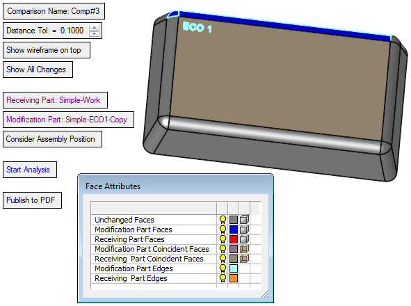
This button starts the comparison analysis. Once the analysis is complete, the following occurs:
|
||||||||
|
Publish to PDF |
Publish to PDF to create 3D PDF files that include parts and assemblies from Cimatron. When this button is selected, the Publish to PDF dialog is displayed giving you additional controls before the selected entities are exported to PDF. One of these controls enables you to define the output file name. When the Publish to PDF option is invoked from this ECO function, the default name of the output PDF file is composed of the following: <Main_Assembly_Name>-<ECO_Folder_Name>-<Comparison_Name>.PDF In addition, once OK The PDF report is titled, ECO Report, and below the visual area, the names of the Receiving and Modification Parts are displayed. |
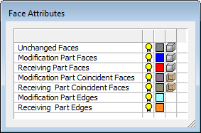
In the example below, the comparison results are displayed showing the modified entities. For additional information on the Face Attributes dialog, see Color-Coded Results.
See the Comparison Notes below.
-
If both parts are the same, a message is displayed indicating that no difference was found between the Receiving and Modification Parts within the specified tolerance. In addition, you are prompted whether on not to mark the ECO Folder <ECO_Folder_Name> as done.
-
If the parts have nothing in common, a message is displayed indicating that no matching faces were found between the two parts.
-
If the parts are identical due to the subtraction of a previous comparison, a message is displayed indicating that the change between the Modification and Previous Modification parts are implemented in the Receiving part. In addition, you are prompted whether on not to mark the ECO Folder <ECO_folder_name> as done.
Optional Step 1 
Unselect faces. Pick unique reference part faces which will not be added to the original part. This option is displayed once the analysis is complete.
By default, when entering this option, all the faces that are marked as changed (including coincident faces) are selected.
The following parameters are displayed:
These options enable you to manually unselect (and select) faces in one of the following groups; either just from the Receiving Part or from the Modification Part or from both. You may also select which split direction faces to keep.
Since the faces of both parts may be placed on top of each other, it may be difficult to understand what selection is made. To solve this problem, use the options below to define which part to select from.
|
Unselect from Both |
Enable selection from both (Receiving and Modification) parts. In any selection of a face, the system looks for the corresponding face from the other part and (if it is found) selects it. |
|
Unselect from Receiving Part: <receiving_part_name> |
Enable selection only from the receiving part. |
|
Unselect from Modification Part <modification_part_name> |
Enable selection only from the modification part. |
|
Select Faces-to-Keep by Split Direction |
Enable the selection of split directions from the modification parts. This will mark the faces that should be kept and used for the compare operation. All these faces are selected, and all other faces are unselected. When this option is selected, a Select Split Direction button You can only select split directions from the modification part. Selecting a face will select the entire direction; unselecting a face will unselect the entire direction. |
|
Reset |
Reset the selection to the default selection. This means that all the faces that are marked as changed (including coincident faces) will be selected. |
 is displayed and activated. Select the split directions and exit.
Notes:
-
By default, when entering this option, all faces that were changed (including coincident faces).
-
When unselecting a face, the edges that mark the face are recalculated.
-
When going back to the required stage, the unselected faces will look as unchanged and will work with that group (in hide/show)
-
Any face that is unselected will go into an Ignore list.
Optional Step 2 
Invoke the Deviation Map function to calculate the distances between the compared parts. This option is displayed once the analysis is complete.
When the Deviation Map function is invoked from the ECO Comparison function, the following occurs to calculate the distances:
The first step of the deviation mapping (setting the original object/faces) is automatically defined as follows:
Modification Part Faces + Modification Part Coincident Faces.
(This data is available once the ECO Comparison analysis is complete - see the Face Attributes dialog shown above).
The second step of the deviation mapping (setting the target object/faces) is automatically defined as follows:
Receiving Part Faces + Receiving Part Coincident Faces.
(This data is available once the ECO Comparison analysis is complete - see the Face Attributes dialog shown above).
The deviation distance tolerance value is set to the default +- 0.05.
The Deviation Map function is displayed at the third required step, ready to run the deviation analysis.
Press OK ![]() in the Feature Guide to complete the function. This creates a new comparison node in the relevant place in the ECO Tree.
in the Feature Guide to complete the function. This creates a new comparison node in the relevant place in the ECO Tree.
|
ECO Tree when invoking the compare operation: |
ECO Tree after the compare operation: |
|
|
|
When editing a comparison, if any of the parts have changed, select the Start Analysis button to show the new comparison result.
|