|
|
UCS (Electrode)  : Options and Results


Access: Open this function from one of the following locations:
-
Select Electrode > UCS > Electrode UCS from the menu bar.
-
Select Electrode UCS from the Electrode Guide.
Create or edit an Electrode UCS (User Coordinate System). This UCS serves as the reference point for this electrode in EDM operations, drawings, and reports.
Notes:
-
The Electrode UCS function can only be used after a Blank has been created and when an electrode is active in an assembly environment.
-
Only one Electrode UCS feature per electrode can be created. If the Electrode UCS function is invoked after an Electrode UCS has been created, the function will be invoked in edit mode (the existing Electrode UCS will be edited; a new Electrode UCS is not created).
Required Step 1 
Pick an origin point for the Electrode UCS. Any point may be picked. This UCS is used as the electrode reference point for reports.
The following toggle option determines whether the origin point is selected manually or automatically. The default option is set in Preferences.
|
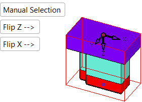
Manual Selection |
Select the required point manually. |
||||
|
Automatic Selection |
The point is automatically selected according to the settings in the Preferences. If this option is selected, an additional parameter consisting of a dropdown list of point options is displayed. The following options are available.
Selecting one of the above options will switch the selection to the relevant point. |
Once the point has been picked, the UCS is displayed. A Flip option rotates the UCS 180 degrees around the X axis.
|
Pick a point to define the electrode UCS origin. |
The UCS is displayed. The default Z direction is as defined in Preferences (either towards the burn faces or the tool holder). |
|
|
|
|
Flip Z: Flip the Z direction around either the X or Y axis, as defined in the Preferences. |
Flip X: Flip the X direction around the Z direction. |
|
|
|


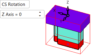
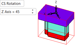
Optional Step 1 
Rotate the UCS, if required, around the Z axis.
The available options are CS Rotation and None. When None is selected, the screen parameters are hidden; click on the appropriate step in the Feature Guide to re-displayed them.
|
|
|
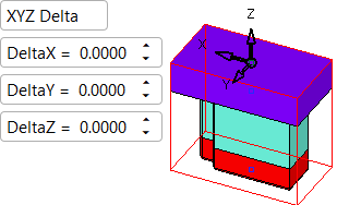
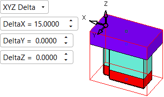
Optional Step 2 
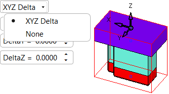
Offset the UCS, if required, by a delta value.
The available options are Delta Values and None. When None is selected, the screen parameters are hidden; click on the appropriate step in the Feature Guide to re-displayed them.
|
|
|
|
|
Click exitexit when finished.
Click OK ![]() in the Feature Guide to complete the function.
in the Feature Guide to complete the function.
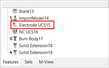
When completed, the Electrode UCS feature will appear in the Feature Tree.

|