|
|
Assembly Mirror  : Options and Results


Access: Open this function from one of the following locations:
-
Click the
button in the toolbar. -
Select Assembly > Copy > Assembly Mirror from the menu bar.
Copy components by mirroring them about a plane.
This function is used to mirror entire assemblies or sub-assemblies with respect to a selected plane while maintaining their structure.
The mirroring can be performed either by creating new parts (Geometrically Mirrored Parts), or, if the assembly to be copied is symmetrical, by adding new instances and placing them in mirrored positions (Positionally Mirrored Parts). When positionally mirroring assemblies, the system automatically determines whether to mirror or copy and rotate an assembly, based on whether it is symmetrical or non-symmetrical.
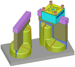
Required Step 1 
- Pick the components to be mirrored.
- Use MMB to <exit><exit> when finished.
Required Step 2 
- Pick the plane about which the parts will be mirrored (the plane can be a planar face or datum plane).
- After the plane is picked, the function moves to the next step.
Required Step 3 
Set the mirroring options. The mirroring parameters are displayed and the preview shows the parts or sub-assemblies mirrored about the plane. The Legend option (see below) displays an information dialog explaining the color codes of the mirrored components.
|
|
|
The following parameters are displayed:
| Position Mirror Symmetrical Parts |
Select the mirroring method for the components to be mirrored about the plane selected in required step 2. The following options are available in the dropdown list:
Notes:
|
||||||||
|
Recreate Electrode Features |
This is a toggle option Recreate Electrode Features / Copy Electrode Geometry that is displayed when using the Copy Mirror All Components option and at least one electrode is selected.
Notes:
|
||||||||
|
Without Cut / With Cut |
Set the With Cut / Without Cut toggle option as appropriate. If the With Cut option is selected, the Cut Manager is displayed in the optional step 1. |
||||||||
|
Options... |
The Options parameter button displays the Mirror Options dialog. The Options button is unavailable when the dialog is displayed.
Use this dialog to control the names and descriptions of new (geometrically mirrored) parts.
|
||||||||
|
Legend |
Display the Assembly Mirror Legend information panel which explains the color codes of the mirrored components. Select the checkbox to create a new sub-assembly for mirrored components for every source component sub-assembly that is copy mirrored.
|
||||||||
|
Associate/Disassociate |
This is a toggle option Associate/Disassociate. By default a mirrored component (Copy Mirrored) is disassociated; see Associativity. This means that the mirrored components are not updated with changes made to the source components. This is reversible, and each component can be turned to Associative mode individually. You may also edit the Mirror feature and change all Mirror Copied components to Associative or Disassociative. If you use Disassociate, the Import Feature that appears in the Feature Tree inside the components (when the function is completed—see below) gets the disassociated icon. If you toggle to the Associate option, they will affect each other (changes made to the source component will affect the mirrored component). This option is only available when at least one part is copy-mirrored. Notes: When editing a mirrored feature:
|
||||||||
|
Apply Changes |
When components previously identified as Symmetrical or Non-Symmetrical are changed geometrically, their status (mirrored/rotated) should usually be updated. Recognized items are marked in yellow. Use the Apply Changes button to update their status. |
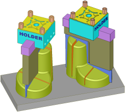
Change Mirroring Method for Individual Parts
Regardless of the mirroring method selected, you can change the method for each part individually. For example, you can define that all catalog parts would be only positionally mirrored, or choose to geometrically mirror every part.
Pick the mirrored part whose mirroring method is to be changed; a label containing a dropdown list of mirroring options is attached to the picked part. Select the appropriate option.
For example:
|
In this example, the mirrored "Slide" part is picked. This is the mirrored part whose mirroring method is to be changed. |
The label containing a dropdown list of mirroring options is displayed: |
|
|
|
The following options are available:
|
Copy Mirror |
Geometrically mirror the selected component about the plane, in the same way as the Copy Mirror All Components option above. |
||||
|
Rotate <axis> |
Positionally mirror the selected component about the plane according to an axis of an additionally selected symmetry plane. These parts are copied as rotated/transformed instances. The result is a part that is an instance of the original part; see the Tree Structure of Mirrored Parts, below.
Example results of changing the orientation:Example results of changing the orientation:
|
Optional Step 1 
The Cut Manager is displayed if the With Cut option is selected in step 3; select the parts to be cut. This step is used to manually control which parts are to be cut.
Click OKOK![]() or ApplyApply
or ApplyApply![]() in the Feature Guide to complete the function.
in the Feature Guide to complete the function.
When completed, the Assembly and Feature Trees are updated, see Tree Structure of Mirrored Parts below.
Tree Structure of Mirrored Parts
When the function is executed, the Assembly and Feature Trees are updated, according to the mirroring method selected.
The Assembly Tree before the Assembly Mirror operation:
The Assembly Tree after the Assembly Mirror operation according to the mirroring method selected:
|
Copy Mirror All Components |
Position Mirror Symmetrical Catalog Parts |
Position Mirror Symmetrical Parts |
|
The result is a new component for each part mirrored (a new mirror and import feature is created in the Feature Tree of the mirrored assembly or part respectively). In this example, all the mirrored parts are new components. |
All catalog components are positionally mirrored; the result is an instance part of the original part. All non-catalog components are geometrically mirrored; the result is a new component for each part mirrored. In this example, the Slide_Mirror part is a new component, all the other mirrored parts are instances or the original part. |
All symmetrical components are positionally mirrored; the result is an instance part of the original part. All non-symmetrical components are geometrically mirrored; the result is a new component for each part mirrored. In this example, all the mirrored parts are instances or the original part. |
|
|
|
|
The Feature Tree of the assembly after the Assembly Mirror operation:
|
An Assembly Mirror feature is added under a Copy Operations leaf. |
|
|
The Feature Tree of the geometrically mirrored part after the Assembly Mirror operation:
|
The geometrically mirrored feature is shown as an imported feature. |
If the mirrored part has more than 300 faces, the mirrored feature is shown as a disassociated ( |
|
|
|
 ) imported feature.

|