|
|
Automated Drill: Define/Modify Sequence 
![]()
![]()
Access: Open this function from one of the following locations:
Select an Automated Drill procedure (from the Process Manager) and choose one of the following:
-
Select NC Utilities > Automated Drill > Define/Modify Sequence from the menu bar.
-
Select the appropriate group (see the note below) and then select NC Utilities > Automated Drill > Define/Modify Sequence from the menu bar.
-
Select the appropriate group (see the note below) and then select Define/Modify Sequence from the Automated Drill Guide.
-
Double-click the appropriate group (see the note below).
-
Right-click the appropriate Unassigned Group in the Group and Sequence Manager and select Define Sequence from the popup menu.
Note: The appropriate group can be either a Sequence Group or Unassigned Group.
Define/edit a Hole Sequence.
A Hole Sequence is a set of faces describing a hole.
This function enables you to pick a group of holes, define a technological process (drilling sequence) to machine the holes and attach the drilling sequence to the group.
When invoking the function without first selecting hole or group of holes, the following grayed out parameters are displayed:
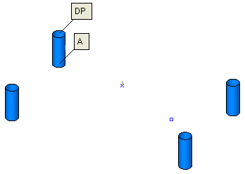
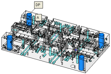
Pick a group of holes.
Pick a hole or drill point belonging to the appropriate group or pick a group from the Group and Sequence Manager.
|
All the holes in the group are highlighted when a hole or group (from the Group and Sequence Manager is picked.
|
|
|
|
|
Press <exit><exit> when finished.
You now need to define or edit a drilling sequence for the selected group and attach the sequence to the group. The sequence definition is done by filling a table with the drill cutter order and parameters. This table can either be filled manually, or from the Cutter Table or from a sequence catalog.
When <exit><exit> is pressed the following actions occur:
The system performs a geometrical analysis on the group of holes (or from the catalog in the case of a group without geometry).
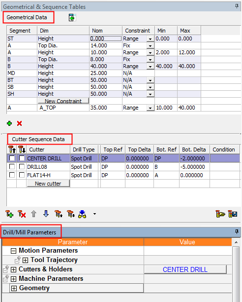
The following tables are displayed on the left of the Cimatron window:
|
|
Geometrical Data table Cutter Sequence Data table Drill/Mill Parameters - specifically the Tool Trajectory Parameters These tables, when completed, define the drilling sequence for the group of holes. |
The parameters are displayed activated.
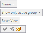
Parameters
|
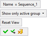
Name = Sequence_<n> |
The default sequence name - where n is an increasing integer. |
||||||||
|
Show only active group |
The following dropdown options are available:
|
||||||||
|
Reset View |
Reset the view to the initial display for this step. If you ZPR away from this view, you can return to the view by clicking the Reset View button. |
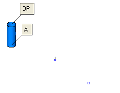
The selected hole axis is aligned with the screen display in transparent mode, with the drill point oriented to the top and the hole centered in the graphics display.
|
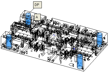
On some occasions, depending on the proximity of neighboring holes, the display of the selected hole may be difficult to visualize. |
In these cases, pick another hole to increase the clarity. |
|
|
|
|
The system automatically aligns the selected hole with the screen and displays the anchor point labels. |
|
|
|
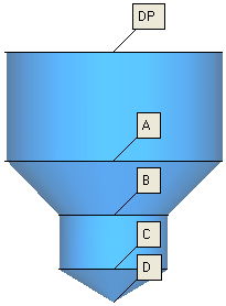
Anchor points are displayed signifying each segment of the hole.
Anchor points are points along the hole axis that are used when defining the parametric drill heights.
Depending on the type of hole, the number of anchor points signifying each segment (A, B, C, D, etc.) may differ. These anchors are named according to their location - A is the closest to DP, then B, etc.
|
|
|
|
|
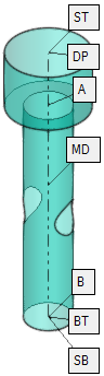
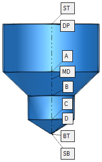
Each anchor point (denoted by a unique letter(s) - unique for each hole) specifies the area from the anchor to the segment above. For example, segment D covers the area from the anchor of segment D up to the anchor of segment C.
Additional anchors define specific points of a hole.
|
ST |
Stock Top: The stock height
from the top side.
|
|
DP |
Drill Point: The upper point
of the geometric hole.
|
|
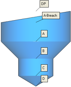
Breach |
Breach: The highest point at which the hole is surrounded by walls. The Breach refers to the top segment of the hole. |
|
MD |
Mid Point: The mid point of
length of the hole. This anchor point is used for reference only, as a
height for drilling operations, mostly for drilling from both sides.
|
|
BT |
Bottom Point: The bottom of
a hole. This anchor point enables the same sequence to fit more hole variations
from the same hole family. In gun drilling for example, intersections
will not require special sequences.
|
|
SB |
Stock Bottom: The stock height
from the bottom side.
|
|
SH |
SH: The total depth of the hole
as required; either as (SH=ST-BT)
or as (SH=ST-SB).
|
Notes:
-
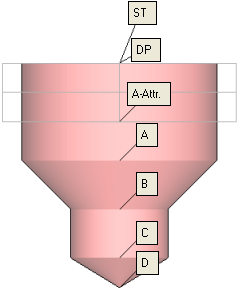
Anchor points can be assigned to the Top and Bottom Reference parameters in the parameter table, either graphically by right-clicking an anchor and selecting the appropriate parameter, or by a dropdown list of anchor points, in the parameter table.
-
When an Automated Drill procedure is divided by a Cutter Change, the comment of the created procedure contains the sequence name.
The <Sequence Name> is defined as follows: If all motions in the created procedure belong to a single sequence, then it is the name of that sequence, otherwise the name is Multi Sequence.
The format of the comment is as follows: <Sequence Name> N of M <old procedure's comment>.
For example:
Single sequence: Through 16 H=27 9 of 14 No Text
Multi sequence: Multi Sequence 7 of 14 No Text
See Also
When finished, press one of the following approval options (these options are initially grayed out):
|
OK: Accept the changes, perform the operation and close the current dialog/task. |
|
Apply: Accept the changes, perform the operation and keep the current dialog/task open. |
|
Cancel: Cancel all changes and close the current dialog/task without saving the settings. |
|