|
|
Parametric Expressions/Relations 

Access: To enter parametric relations/expressions into the Edit Parameters dialog:
-
Display the Edit Parameters dialog or the Sketcher Dimension dialog.
-
Pick the dimension whose value is to be an expression.
-
From the dialog displayed in step 1, press the Create Relation button
to enter expression
mode.
When editing numerical values of a feature, you can assign dimensions in the form of algebraic equations. These equations can consist of numbers only (i.e. 5+6*3) or they can relate to other parameters to create equations with parametric dependency.
Simply click on other dimensions (reference dimensions) to enter their ID's into your equation, and then enter the desired mathematical operation. A dimension, whose ID is part of an expression for another dimension, is called a reference dimension (a reference dimension creates a parametric relation between dimensions).
All reference dimensions must be displayed in order to be used in an expression (you have to pick the reference dimension to enter its ID into the expression). Dimensions can be displayed or hidden while the Edit Parameters dialog is open by double-clicking on the appropriate features on the Feature Tree or in the graphics area. Reference dimensions are highlighted in the graphics area in a color that differs from the dimension being edited.
Note: While this operation can be performed from the Edit Parameters dialog or the Sketcher Dimension dialog, the examples below use the Edit Parameters dialog.
Parametric relations can be created among the following types of dimensions:
-
Internal (dimensions from the same part)
-
External (between parts in an assembly)
-
Connect parameters
-
Internal expressions inside the Sketcher
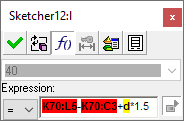
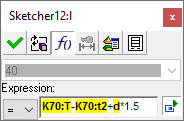
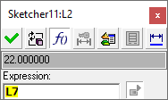
When a reference dimension is added to an expression in the Edit Parameters dialog, its ID appears in the expression field as bold text with a colored background, as shown below with the ID L7:
|
|
The default background color for reference dimension IDs in the expression field, is YELLOW. |
|
|
In the case of Rerouted Relations, where one or more of the reference dimensions participating in an expression are no longer valid (the feature was deleted, the sketch modified, a connection edited, etc.), the background color is RED. |
Each reference dimension in an expression is recognized by a unique prefix, depending from which source the reference dimension was selected:
|
Selected Dimension |
Prefix |
Example |
|
Real dimension inside the same part |
None |
L1 |
|
Real dimension between assembly parts |
Name of the part owner |
Part1:L1 |
|
Connect parameters |
Name of the assembly that owns the Connect + the number of the connect feature |
AA_MD_Fixed Side41:Dy |
|
From an external table |
Setup or symbol |
Setup_die:A (dependent upon the setup format) |
When the expression field is displayed, the dimension field is grayed out and cannot be edited.
Interaction
To modify a dimension value into an mathematical expression:
-
Display the Edit Parameters dialog and access the expression mode (for instructions on how to invoke this tool, press the Access button at the top of this Help topic).
All the dimensions of the relevant feature(s) are now displayed, together with the Edit Parameters dialog showing the expression field.
-
Edit the dimension value as required, in the form of algebraic equations. These equations can consist of the following:
-
Numbers only (i.e. 5+6*3) or
-
They can relate to other dimensions (reference dimensions) to create equations with parametric dependency. These reference parameters are displayed with a yellow background in the expression field. These reference dimensions can be from:
-
The current part - as shown in the example below, where L2 is the dimension being edited and L7 is entered as part of the expression.
-
An external source (Setup dimensions - press the
 button in the Edit Parameters dialog).
 -
The catalog (press the
 button in the Edit Parameters dialog).
-
-
|
|
|
See the Notes and the start to finish example below.
-
Exit the dialog. Note that the edited dimension now has an (f) suffix; this signifies that this dimension is the result of an expression.
-
Permissible mathematical operations:Permissible mathematical operations:
*
multiplication
/
division
+
addition
-
subtraction
sin
sine
cos
cosine
tan
tangent
^
exponential power (i.e. L^2 = L squared, L^0.5 = square root of L)
-
Dimensions must be selected from the display. They are not recognized as such when typed or pasted manually into the expression field, but are regarded as free text.
An exception to this is when dimensions are copied from one dialog to another (for example, copy a dimension in an expression field in one dialog, close the dialog, open the dialog of another dimension, expand it and paste the copied dimension). This kind of copy and paste takes into account the status of shown part names. For example. if copied from a dialog with the part name shown and pasted into a dialog with the part name hidden, then the part name is not included, and vice versa.
Coping and pasting free text (i.e. anything but dimensions) is fully supported. -
The validity of an expression is checked after any change and the dimension field value is updated simultaneously as long as the expression is valid.
The result of a valid expression is displayed in the dimension field in BLACK.
An invalid expression results in the dimension field value being displayed in RED. An invalid expression could be an incomplete expression or a completed expression that is mathematically illegal, such as the following examples:
Part1:L1+-Part2:L1
Part1:L1/0Incomplete expression:
Mathematically illegal expression:
-
If you enter an equation for a parameter, such as extrude length, when you return to the Feature Guide to edit the feature again, this parameter will be grayed out. This is to prevent you from entering a number and overriding the equation.
ExampleExample:Extrude length is defined as an expression (this is denoted by the (f) suffix).
When editing the Extrude feature, the extrude delta value is grayed out.
Parametric Expressions/Relations Example
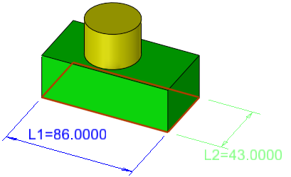
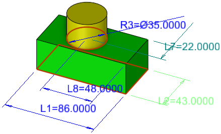
Double-click on both of the features below to display their parametric values. The values displayed include the extrude lengths and dimensions of the sketches.
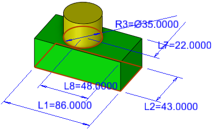
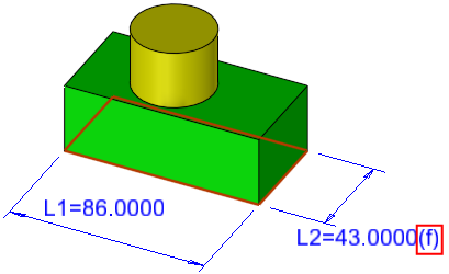
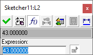
The width of the green object (now 42 [ID=L2]) should be dependent on the distance from the cylinder center to the back of the box (now 21 [ID=L7]). Click the 42 dimension to open the Edit Parameters Dialog, and click the ![]() button.
button.
|
|
|
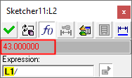
Initially, when creating a new expression, the content of the expression field is the same as that of the dimension field. Now click the 21 dimension to enter its ID (L7) into the equation field.
|
|
|

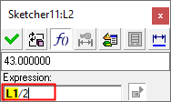
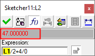
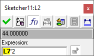
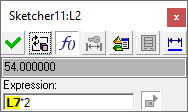
This width value needs to be double the L7 value. Complete the equation as L7*2.
|
|
|
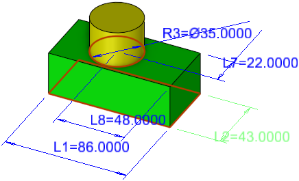
Note that dimensions that take part in an expression (in this example, L7), are highlighted in a color that differs from the dimension being edited (L2) and from uninvolved dimensions. (Setup parameters that are part of an expression are not highlighted). Also note that when the cursor is on a dimension ID inside the expression field (or immediately to the left or right of a dimension ID inside the expression field), the appropriate dimension is highlighted in yet another (third) color. These highlights enable you to immediately view which dimension is being edited, which dimensions take part in the expression and which dimension the cursor is currently next to in the expression field. See an example of the highlighted dimension IDs hereSee an example of the highlighted dimension IDs here.
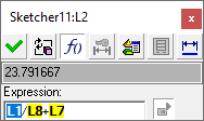
In this example the expression field contains L1/L8+L7. L2 is the dimension being edited and is highlighted in one color; L7 and L8 are referenced in the expression and are highlighted in a second color; L1 is also referenced in the expression, however, the cursor is on L1 in the expression field in the dialog, thereby highlighting it in a third color. The remaining dimensions (L6, L9 and R3) are not involved in the expression and are displayed in the default color.
|
|
|

When you exit the Edit Parameters dialog, notice that the L2 dimension now has an (f) suffix. This signifies that this dimension is the result of an expression.

To add another equation, click on the dimension for the diameter of the cylinder. Click the 44 value (whose ID is L2), and enter the equation shown below.
|
|
|
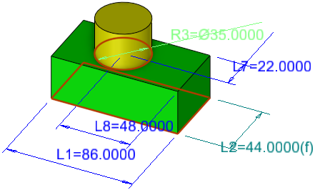
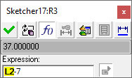
Now whatever the width of the green object is, the diameter of the cylinder will always be 7 less. Notice that the R3 dimension now also has an (f) suffix.
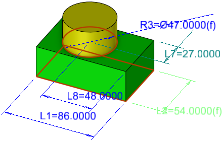
To demonstrate the parametric dependency, change the value of L7 from 22 to 27. Click the ![]() button to update the features.
button to update the features.
|
|
|
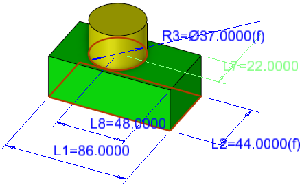
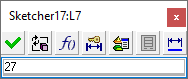
The width of the green object is now 54 (27*2) and the cylinder diameter is 47 (54-7). If you open the Edit Parameters dialog for the width, you will see the equation you entered, rather than the numerical value. The L7 dimension used in the equation (27) is highlighted so that you can immediately see what values were used.
|
|
|
|