|
|
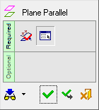
Plane Parallel 


Access: Invoke this function from one of the following locations:
-
Click the
button in the toolbar. -
Select Wireframe > Datum > Plane Parallel from the menu bar.
-
Select Mold Design > Cooling > Parallel Plane from the menu bar.
-
Select Mold Design > Runner > Parallel Plane from the menu bar.
-
Select Cooling > Parallel Plane from the Mold Design Guide Toolbar.
-
Select Runner Design > Parallel Plane from the Mold Design Guide Toolbar.
Create a plane parallel to an existing plane, or to a plane defined by selected entities.
|
Demo: Press the button below to view
a short movie demonstrating the function:
|
Practice: Press the button below to open Cimatron with a practice ELT file similar to that used to create the movie (if the relevant feature already exists in the ELT file, you can either edit it or delete it and create a new feature). |
|
|
|

General Interaction
The following is the Feature Guide for Plane Parallel.
|
|
|
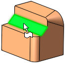
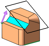
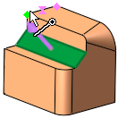
Required Step 1 
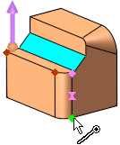
Pick the references entities that define a plane. The following entities can be picked to create the plane:
|
|
|
||||||||||||||||||||||||
|
Planar Face selected |

Notes:
-
If you pick a line, the directional arrow is immediately displayed in the Z direction of the active UCS. This means that you can either press <exit><exit> to immediately display the plane and continue to the next step, or you can pick additional entities to define the required plane and then proceed to the next step.
-
In certain cases, you can pick the entities and then enter the Plane Parallel function. If you do this, the selected entities will automatically be included in Step 1.
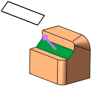
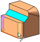
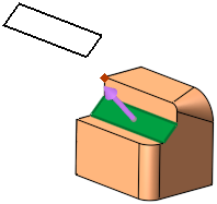
Required Step 2 
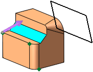
You can locate the plane on one or both sides of the reference geometry selected in Step 1. You can also fine tune the position of the parallel plane either by offsetting a Delta amount in a specific direction, by selecting a Point and (if required) offsetting from that point in a specific direction, or (when using the Both Sides option) you can set a mix of options - By Point on one side and By Delta on the other side.
 |
|
|
|
|
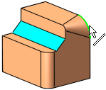
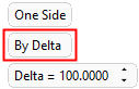
One Side: By Delta |
|
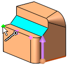
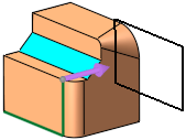
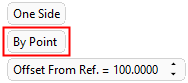
One Side: By Point |
|
|
|
|||
 |
|||
|
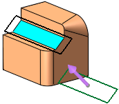
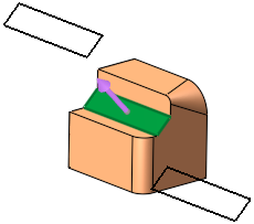
Reference entity selected in stage 1 |
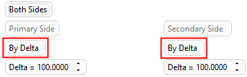
Both Sides: By Delta, By Point or mixed (one side by Delta and the other side By Point - as in the image above) |
||

Parameters
|
One Side / Both Sides |
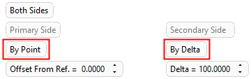
This is a toggle option to create the plane either on One Side or Both Sides of the selected reference geometry. When One Side is selected, the plane is created in the offset direction indicated by the direction arrow. When Both Sides is selected, a plane is also created in the opposite direction, creating planes in both offset directions in a single operation. When switching from Both Sides to One Side, the plane on the direction arrow side remains. When using the Both Sides option, the location of the planes needs to be defined at both the Primary and Secondary Sides. Both sides can be defined using the options By Delta, or By Point or mixed, with one side By Delta and other side By Point, as shown in the example below: When using Both Sides with a mix of options (By Point on one side and By Delta on the other side), indicate the Primary direction and the delta value/reference point.
|
||||||||||||
|
By Delta / By Point
|
This is a toggle option By Delta / By Point to set a location at which the plane will be created, in the direction indicated by the direction arrow and parallel to the geometry selected in stage 1. |
||||||||||||
|
By Delta |
Set the Delta distance from the geometry selected in stage 1, at which the plane will be created.
|
||||||||||||
|
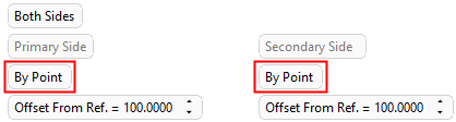
By Point |
Select a reference point at which the plane will be created, parallel to the geometry selected in stage 1. The Offset from Ref. option sets an offset distance from the selected reference point, at which the plane will be created. Pick the point(s) through which the plane(s) will pass. Use the direction arrow to set the offset direction.
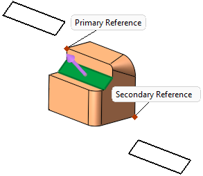
When using the Both Sides option and with By Point, pick the Primary and Secondary Reference points at which the planes will be created. The Primary and Secondary reference points are labeled as they are picked, as shown in the example below. The Offset from Ref. option is available to set an offset distance from one or both reference points.
|
||||||||||||
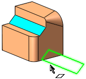
When you are finished, <exit><exit> to complete the step, and press OK ![]() or Apply
or Apply ![]() in the Feature Guide to complete the function.
in the Feature Guide to complete the function.
The datum plane now appears, with drag handles for resizing.
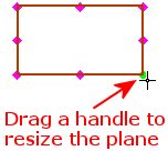
Note: The default size of plane drag handles can be set by editing the Plane Grab Handle size value in the General Preferences > Datum Planes.
When completed, the Plane-Parallel feature will appear in the Feature Tree as follows:
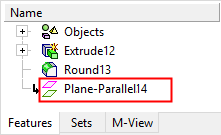

|