Measurement  > In-Process Measurement
  : Typical Scenario
![]()
![]()
Access:
-
For Technology, choose Measurement as the main selection and In-Process Measurement as the subselection.
A typical In-Process Measurement scenario on the CNC machine is as follows:
Home Setup Adjustments
-
The part is mounted on the machine.
-
Relevant measurements are taken.
-
Home setup adjustments are made according to these measurements: C alignment, X Y & Z position.
Milling Process
-
Relevant milling operations are executed. For example, a slot is milled.
Measurement and 'Looping'
-
The part is measured. For example, the width of the slot is measured.
-
According to measurement results, conditional operations are executed. For example, adjusting the cutter compensation value and repeating the slot cutting operation. This 'loop' can be repeated as long as necessary according to the user's input.
Measurements of the Completed Part
-
The part is measured to verify its final dimensions. For example, the final width of the slot is measured.
-
As a result, actions can be taken, such as to resume the milling process, issue a program stop, or output reports.
In-Process Measurement - Process logic
This section describes how to define an In-Process Measurement procedure.
Step 1: Create an In Process Measurement procedure
Step 3: General procedure inputs
Step 1: Create an In-Process Measurement procedure
As any NC procedure in Cimatron, an In Process Measurement procedure is created through the Process Manager, but instead of milling a part it performs measurement operations.
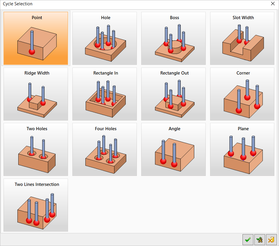
Step 2: Cycle selection
Select one of the Cycle Operations below.
Step 3: General procedure inputs
Select a probing tool, stylus, and holder from the Cutters & Holders Dialog.
Set the other procedure parameters (Clearance & UCS, Tolerance & Surf. Offset, etc.).
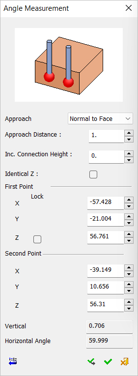
Step 4: Cycle data input
Set the cycle data input, either by picking from the screen or by typing in the cycle's specific parameters.
The following image shows the parameters available for the Angle Measurement Cycle.
Step 5: Action
This step is the heart of the measurement procedure. Here you decide the actions that determine the measurement results.
The following action types are available, listed below in their order of appearance in Cimatron.
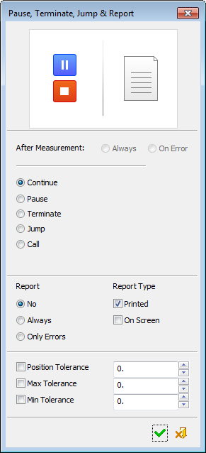
Action 4: Pause, Terminate, Jump & Report
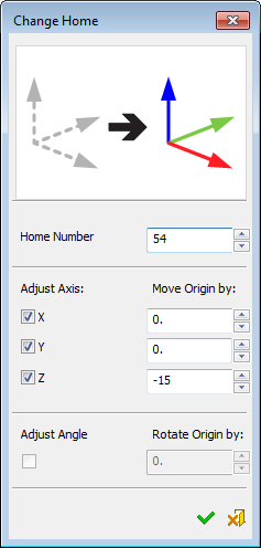
Action 1: Change home
Change Home: Using the measured data, the program can instruct the controller to change the home settings.
Adjust the home coordinate system orientation. This is called C Alignment.
Adjust the X, Y or Z position. This is called Home Setup.
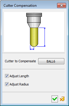
Action 2: Cutter Compensation
Cutter Compensation: Using the measured data, the program can instruct the controller to store or change the cutter compensation value registers.
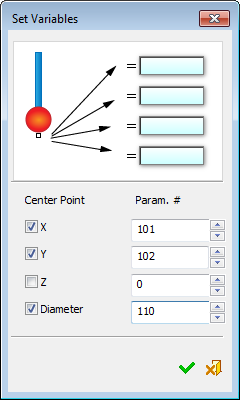
Action 3: Set Variables
Set Variables: Using the measured data, the program can set values into controller registers.
Action 4: Pause, Terminate, Jump & Report
Pause, Terminate, Jump & Report: If any issues are detected by the probe (for example, a deviation or a measurement beyond the allowed tolerance), parameter settings in this dialog can instruct the system to perform corrective actions by repeating the milling operation.
Additional options are available, such as to stop or continue the program.