|
|
Measurement  > In-Process Measurement
![]()
![]()
Access:
-
For Technology, choose Measurement as the main selection, and In-Process Measurement as the subselection.
Optimize milling processes combined with feedback from part measurements while the part is on the CNC machine. This procedure performs part measuring operations on the CNC machine and validates the current machining results. You can chose whether to fine-tune successive machining operations (for example, change the cutter diameter compensation value) or to stop the machine to avoid out of tolerance machining.
The Measurement procedures are an integrated solution to On Machine Measurement. This means that the system utilizes the CNC machines not only to mill the part, but also to use probes to measure the machining result.
The measurements are performed during the milling process or at its end, as single or multiple measurement operations.
One measurement cycle can be defined per procedure. The most common measuring cycles are available, each with parameters to control the motions and other aspects of the process. For each cycle, you can instruct some actions to take place on the machine after the measurement has finished. These actions enable the use of the same cycle for different purposes.
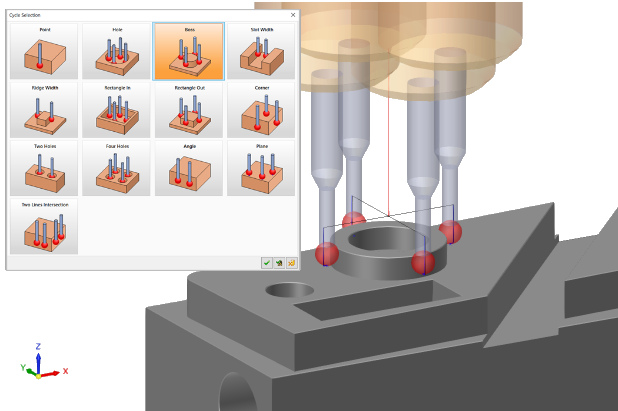
The image below shows a selection of measurement cycle types and measurement points picked on the model. In this case, a Boss measurement cycle is selected and the result is the displayed probing path. A measurement tool (probe) is required for the procedure operations. The measurement probe can be defined similar to all other tools, in the Cutters and Holders Dialog.
The procedure definition consists of the following parts:
-
Procedure definition: Definition of the measurement type to be performed.
-
Procedure action: The action that the milling machine will perform with the measurement results.
Notes:
-
When using the Measurement procedures, a measurement tool (probe) is required for the procedure operations. This measurement probe can be defined similar to all other tools, in the Cutter Parameters tab of the Cutters and Holders Dialog.
-
Running the Measurement procedures create tool motions as close as possible to the motions of the measuring probe during "machine" time. These motions are displayed in the Navigator and Simulator, and you can step through them like all other tool motions. However, since in most cases the output from such a procedure to the machine is not a set of motions but a special cycle or a macro call, the true nature of the motions is actually determined on the machine itself, according to the way it was programmed. There are also some differences between the different controls. What is shown in Cimatron are some motions that best represent the nature of the different cycles.
How to create this procedure
(See Creating a Procedure for a general explanation.) See Typical Scenario for additional information.
For Technology, choose Measurement as the main selection and In-Process Measurement as the subselection.
Choose the appropriate measurement probe.
Set the Geometry parameters.
Define the following Motion Parameters:
Define the Machine Parameters.
When finished, you can choose from the following Work Mode Dialog buttons:
(These options are also available on the Procedure popup submenu.)
If Save & Calculate is selected, the Process Manager displays the transformation procedure and indicates which source procedures participated in the transformation and whether they were merged into the transformation.
|