|
|
Shell  : Options and Results


Access: Open this function from one of the following locations:
-
Click the
button in the
toolbar. -
Select Solid > Objects > Shell from the menu bar.
Turn a solid object to a shell or add thickness to an open object.
Required Step 1 
Pick a solid object. An open object may also be picked. If only one object exists, it will be automatically picked.
Required Step 2 
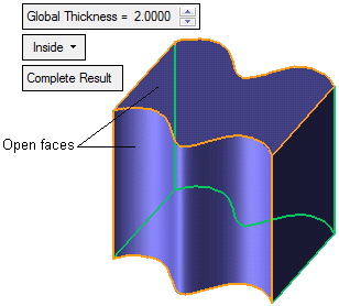
Pick the open faces and set the parameters.
Specify open faces, shell direction, and global shell thickness. If you do not pick any open faces, the object will be hollowed only in the middle.
|
Global Thickness |
Set the global thickness value for all selected faces. Local (non-uniform) shell thicknesses values can be set for specific faces in the Optional Step 1; see below. |
||||||||||||||
|
Inside |
This is a dropdown list of options which defines the shell direction. The following options are available:
Note: If you are creating a shell on an open object, a direction arrow will appear indicating an inside or outside direction. You can either click the arrow to toggle the direction, or select the Inside / Outside option from the dropdown list.
|
||||||||||||||
|
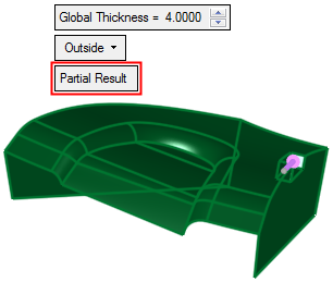
Complete Result |
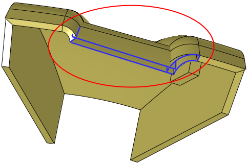
This is a toggle option Complete Result / Partial Result, that enables you to select a partial result in cases where the operation fails.
|
Optional Step 1
Set local (non-uniform) shell thicknesses values for specific faces. See Optional Step 1. By default, all faces are offset by the same amount - the Global Thickness value specified in Required Step 2.
Note: The Non-uniform shell is available only for closed solid objects (it is not available for open objects).
When you have finished setting parameters and picking open faces, press <exit><exit>.
If this is the final result, click OK ![]() or Apply
or Apply ![]() in the Feature Guide to complete the function.
in the Feature Guide to complete the function.
When completed, the Shell feature will appear in the Feature Tree as follows:

|