|
|
Trimming Punch  : Options and Results


Access: Open this function from one of the following locations:
-
Select Die Design > Punch Tools > Trimming Punch from the menu bar.
-
Select Trimming Punch from the following Die Design Guide: Die Tool Design Guide.
Create a trimming punch and create pockets for it in the relevant plates.
The system automatically creates the punches according to your specifications, cuts through plates to position the punches, and establishes dimensions of the matrix, die backing plates and die shoes.
Select a planar face (punch) or a planar wire; the system then creates the necessary cutting objects and performs a cutting operation on all relevant parts.
This is an assembly feature tool that is opend when a part is activated or non-activated in the assembly environment. You can perform the Trimming Punch operation using the following options:
Note: When editing the Trimming Punch feature, only the plates that are included in the cut will be shown in the Cutting Objects dialog. See Trimming Punch - Editing.
Required Step 1 
-
Pick a 2D Contour(s) or Face(s). The following parameters are displayed; click the dropdown list to display the available options:
Displayed parameters:
Displayed parameters showing the dropdown list options:
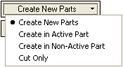
Option
Description
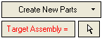
Use this option to create multiple new parts under the selected assembly and then perform the trimming punch operation on these parts. Click here for an example.Click here for an example.
-
Select the Create New Parts option.
-
Click the arrow
 next to the Target Assembly field and then select the target assembly. The selected assembly name is displayed in the Target Assembly field, as shown below:
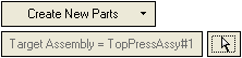
-
Pick the new parts. Multiple parts can be selected by picking faces or 2D contours. For each face/contour selected, a label is displayed indicating the part name, as shown below:
Pick a label to edit the assigned part name. If invalid characters are entered, an appropriate message is displayed. If a part name already exists, a message is displayed and the last valid name is restored.
-
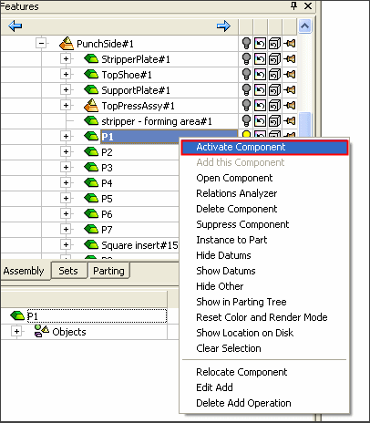
Use this option to perform the trimming punch operation in an activated part. Therefore, before accessing the Trimming Punch operation, you must activate a part in the assembly. Click here for an example.Click here for an example.
-
In the die assembly tree, right-click the selected part and select Activate Component from the displayed a popup menu,
-
open the Trimming Punch function.
-
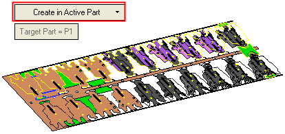
Select the Create in Active Part option,
Note: The
 button is grayed out to indicate the P1 activated part is selected and cannot be changed at this stage.
-
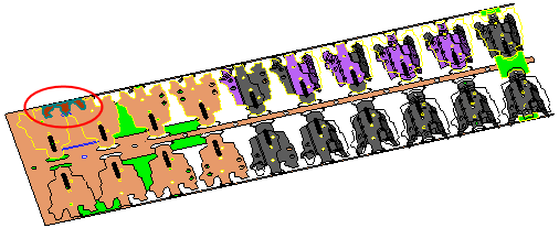
Pick a 2D Contour as shown below (marked in red).
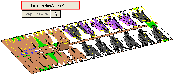
Use this option to perform the trimming punch operation in a non-activated part. Therefore, you must select an inactive part from the required assembly. The Trimming Punch operation will then be performed on this inactive part. Click here for an example.Click here for an example.
-
Select the Create in Non-Active Part option.
-
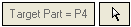
Select a non-active part in the selected assembly, as shown in the example below:
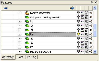
Pick a 2D Contour as shown below (marked in green).
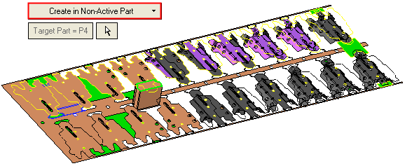
Note: The
 button is dimmed to indicate the P4 inactive part is selected and cannot be changed at this stage.
 -
Use this option to cut surrounding components, without actually creating the punch part itself (for cases where a catalog punch is used). Click here for an example.Click here for an example.
No other parameters are displayed in this step.
-
Select the Cut Only option.
-
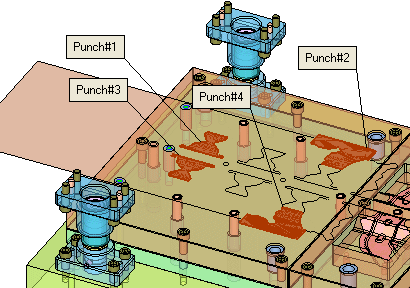
Pick 2D closed contours or planar faces. If required, pick more than one face. See Multiple Punch Operations.
-
-
Required Step 2 
-
Define the punch parameters.
A punch has now been added, as shown in the picture below. The default values of the punch parameters defined in this procedure are derived from Die Setup. In this stage, you define the extrude value and whether it will appear on the upper or lower side of the strip and more.
The following options are displayed:If the Create New Parts or Create in Non-Active Part options were selected in the 1st required step.
If the Cut option was selected in the 1st required step.
For further information of these parameters, refer to DieSetup.
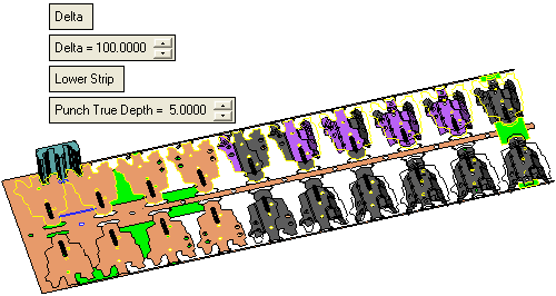
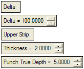
Delta / Reference
This is a toggle option: Delta / Reference. Set how the extrude is to be created:
Delta
The extrude is created on one side, with a given value. The following additional parameter is displayed:
Delta =
Enter the delta distance for the extrude.
Reference
Set the direction and choose the reference face to which the contour will be extruded, as described in Example: To Reference: Upper Strip.
For further details on these options, refer to Extrude.
Upper Strip / Lower Strip
This is a toggle option: Upper Strip / Lower Strip. Define on which side of the strip the extrude is to be created:
Upper Strip
Create the extrude on the upper side of the material strip. The following additional parameter is displayed:
Thickness
Enter the thickness of the workpiece.
See DieSetup.
Lower Strip
Create the extrude on the lower side of the material strip. See DieSetup.
Punch True Depth
Enter the depth of the punch through the strip.
Note: The direction of the extrude is always in the normal to the strip plane direction, therefore no arrows are required here.
-
Define the punch parameters as required. For more on the To Reference and Upper Strip options, see this exampleexample.
Create a new part under the selected assembly using the To Reference option.
-
From the Assembly tree, select the face to which the contour will be extruded. In our example StripperPlate is selected:
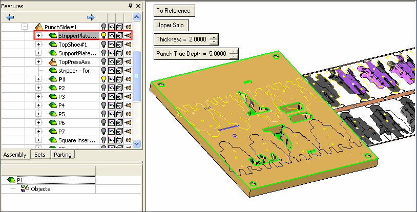
-
Toggle the selected StripperPlate icon to the hide
 position, to hide the selected plate:
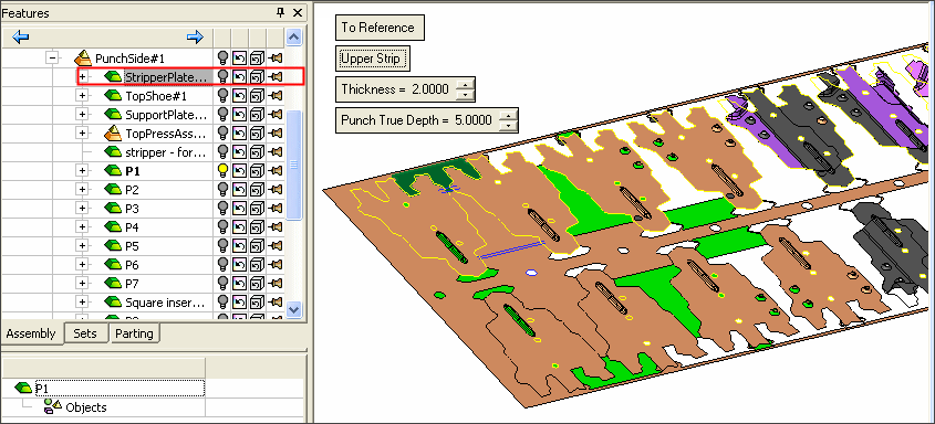
-
Set the Reference parameters.
-
-
ExitExit the step. Step 3 will define the cutting objects for the plates, including parameter values, attributes and more.
Required Step 3
-
Define the cutting offsets and shapes.
The Cutting Objects dialog is displayed. If the Create New Parts option was selected in the 1st required step, a With Cut/Without Cut toggle option is displayed; in this case, the Cutting Objects dialog is displayed if the With Cut option is selected.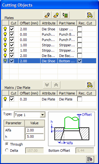
The Cutting Objects dialog includes the following
Buttons:

Hide Entire Assembly: Hides the entire assembly.

Show Entire Assembly: Displays the entire assembly.

Recalculate: Perform the calculations again.

Preview: Display a preview of the cut.

Define as Die (Cutting with Draft Angle):

Define as Straight Cutting Tool:
-
To define cutting offsets and shapes, select the plate to cut from the Plates pane, as shown in the following image. (In this case select the StripperPlate marked in red.)
-
Click the Define as Die (Cutting with Draft Angle)
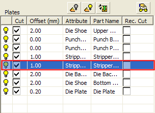
button to move this row to the Matrix/Die Plate pane, as shown below: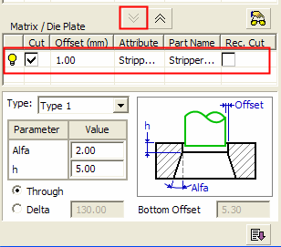
-
In the Matrix/Die Plate pane, set the parameters as required.
Notes:
-
Click the
Preview button at the top of this pane to display a preview of the cut. -
Click the
button to move a selected row from the Plates pane to the Matrix/Die Plate pane. Each time this button is pressed, another selected row is added to the Matrix/Die Plate pane. -
Click the
button to move up a plate from the Matrix/Die Plate pane (where the components are tapered cut) to the Plates pane, (where the components are not tapered cut). If more than one component is available in the Matrix/Die Plate pane, this button is only available when a specific component is selected in the pane.
-
-
Click OKOK
 or ApplyApply
 in the Feature Guide to complete the function. The new part (Punch002), is displayed under the selected assembly:
Optional Step 1: 
-
Add a wedge body on top of the punch body, for fastening purposes.
This optional stage becomes enabled after completing Required Step 1 only after having a preview of the punch body). If the Cut Only option is selected in Required Step 1, then this optional stage is dimmed.
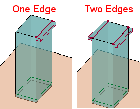
Pick straight, circular or chained edges and set the parameters to define the wedges. The display is updated according to the number of edges you pick and also the currently defined parameters.Notes:
-
Pick one edge for a single wedge or two edges for a double wedge.
-
Edges can be picked in more than one punch; this means that wedges can be created simultaneously in a few punches, according to the dimensions specified (in the appropriate tab of the Fastening Details dialog or in the parameter box displayed for each selected edge).
-
All the picked edges must be on the top punch face.
-
-
Various types of edges can be selected at once:
In this step, the Smooth Chain On/Off toggle option is displayed as well as the Fastening Details dialog.
Select the required option and set the appropriate parameters in the dialog.-
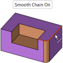
Smooth Chain On/Off
Edge Selection: Picking Edges - Smooth Chain On/Off
Edge Selection -
Smooth Chain Off
Pick an edge. Only the picked edge is selected. Pick other edges as required.Edge Selection -
Smooth Chain On
Pick an edge. All edges connected to the picked edge in a smooth chain (no sharp corners) are automatically selected.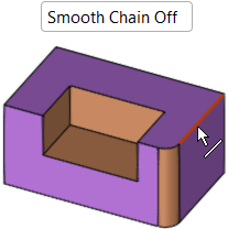
-
Fastening Details
The Fastening Details dialog is displayed with the relevant parameters in each of the tabs appropriate to the type of edge selected. These tabs display the global wedge and cutting dimensions, according to the type of edge selected - Options are Straight Edge, Circular Edge, or Chained Edge, as shown below.
Wedge dimensions can also be set locally for individually selected edges, for more see Setting Local Wedge Parameters.Straight Edge parameters:
This tab is displayed if a straight edge is selected.
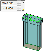
The wedge dimension L is set locally for each selected edge. The W and H values are set globally in the dialog, but can, however, also be set locally.
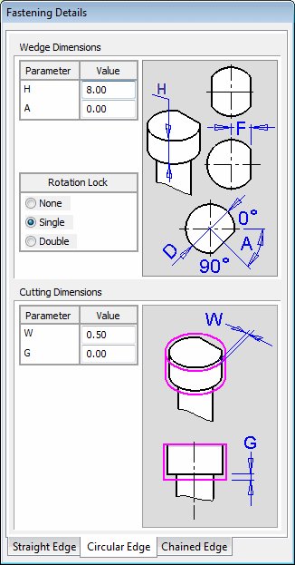
Circular Edge parameters:
This tab is displayed if a circular edge is selected.
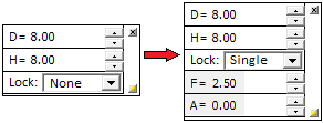
The wedge dimensions D and F are set locally for each selected edge. The H and A values are set globally in the dialog, but can, however, also be set locally.
In the dialog, the A value is empty and dimmed if Rotation Lock = None.Chained Edge parameters:
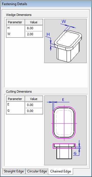
This tab is displayed if a chain of two or more edges is selected.
The wedge dimensions W and H are set globally in the dialog, but can, however, also be set locally.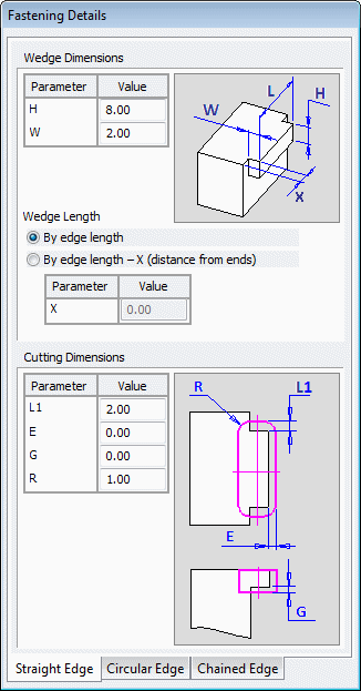
Setting Local Wedge Parameters
The parameters for each edge can be set locally by selecting the + figure displayed on every selected edge. This displays a local parameter box with parameters specific to the type of edge selected. When the parameters for an edge are displayed, a O is displayed in place of the +; thus, even is the parameter box is hidden, the O signifies that individual local parameters may have been defined. A different parameter box is displayed for each type of edge selected:
Straight Edge parameters
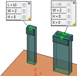
The parameters on the left are the result of selecting By edge length in the Fastening Details dialog, above.
The parameters on the right are the result of selecting By edge length -X (distance from ends) in the dialog. With this option, the X value may be positive (to reduce the length from the ends) or negative (to extend the length beyond the default edge length). The default = 0. When this option is selected, the L value is a result of the X value.
Circular Edge parameters:
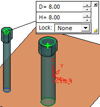
If the Lock parameter is other than None, the parameter box is expanded to display additional parameters:
Chained Edge parameters
In this case, the selected contours can also be open:

-
-
Each parameter box displays two buttons:

Close the parameter box and to revert the locally set parameter values of the edge to those of the current values displayed in relevant tab of the Fastening Details dialog.

Hide the parameter box of the relevant edge. The edge is still denoted by a O, signifying that local parameter values have been set.
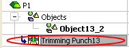
- When completed, the Trimming Punch feature will appear in the Feature Tree
|