|
|
Add Component: Place on Face


Access: Open this function from one of the following locations:
Add Component
-
Click
 in the toolbar.
 -
Select Assembly > Main Tools > Add Component from the menu bar.
-
Select Add Component in the popup menu when no geometry is selected.
Add a Duplicate Copy
-
Click
 in the toolbar.
 -
Select Assembly > Main Tools > Add a Duplicate Copy from the menu bar.
-
Select Add a Duplicate Copy in the popup menu when no geometry is selected.
-
Select Add a Duplicate Copy from the Mold Design Guide Toolbar.
Add Electrode
-
Select Electrode > Add Electrode > Add Electrode from the menu bar.
Function variations
|
Add Component |
Add a component to the assembly / sub-assembly. |
|
Add a Duplicate Copy |
Add a component that is a duplicate copy of an existing component, to the assembly / sub-assembly. Add a Duplicate Copy is used you to bring mechanisms, assemblies and other components that you have used in previous projects. Add a Duplicate Copy is similar to Add Component, however, Add a Duplicate Copy creates a free copy of the component and allows you to add it to your current assembly without affecting the original assembly. |
|
Add This Component |
Add a preselected component to the assembly / sub-assembly. |
|
Add Electrode |
Add an existing electrode part. |
Required Step 2 
Place the component. The options displayed depend on the type of entity to be added:
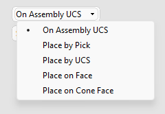
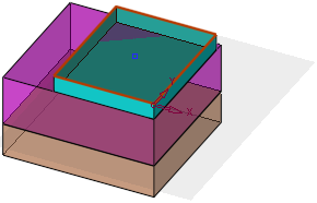
Place on Face
Select Place on Face and pick the face on which to place the component.
|
Pick the face on which to place the component. |
|
|
|
|
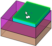
The Place on Face parameters are displayed and the selected face is displayed at 75% transparency.
|
Pick the UCS on which to place the component. |
|
|
|
|
If a Catalog component is being added, the Edit Parameters parameter is also displayed.
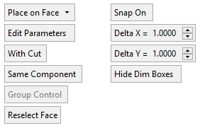
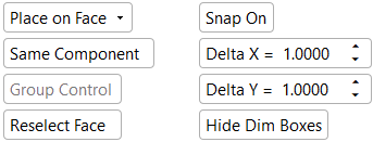
To pick a different face on which to place the component, select the option Reselect Face and pick the required face.
The Snap On / Snap Off option is displayed. Use the feature to snap to a location when positioning a component. If Snap On is selected and the Grid is displayed, additional parameters are displayed (see Snap On / Snap Off).
The Sketcher toolbar is displayed, set to Points by default. Right-click in the graphics area to display additional options in a popup menu (see the Reference Component example).
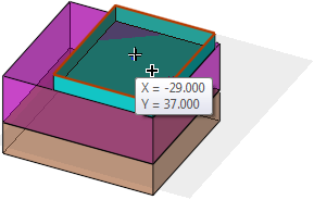
Pick the locations on the face or anywhere else in the graphics area where you want to place the component.
If the Snap On option is selected, the XY coordinates are displayed when the cursor is moved and change by the amount defined in the Snap On parameters.
|
XY coordinates are displayed when the cursor is moved. |
|
|
|
|
At each pick location, a sketch point entity is created (in the activated assembly file) and the component is added.
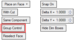
After placing the first component, the optional steps of the Feature Guide become available.
If more than one instance of a component is added, the Group Control option becomes available. This provides Group or Individual control over the parameters of each instance.
|
XY coordinates are displayed when the cursor is moved. |
|
|
|
|
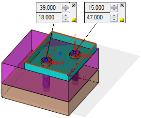
If the Snap On option is selected, the XY parameters are displayed in a dialog when a location is picked. These are the Dimension Boxes.
At this stage, you can also pick a reference component to place the added components on the same array as other components. For more, see the Reference Component example.
- Adaptive Diameter Control of Added Parts
- Picking a Reference Component - Example
- Edit Parameters - Example
Press MMB to <exit><exit> when finished.
Click OKOK![]() or ApplyApply
or ApplyApply![]() in the Feature Guide to complete the function.
in the Feature Guide to complete the function.
|