|
|
Edit Split Direction 

Access: Open this function from one of the following locations:
-
Right-click on a split directionsplit direction(for example,
 )
in the Parting
Tree and select Edit Direction.
)
in the Parting
Tree and select Edit Direction. -
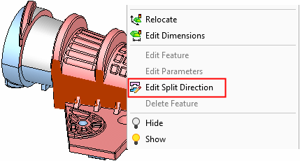
Right-click on a face that is attached to a QuickSplit direction and select Edit Split Direction.
See the note below.
|
Invoke from a split direction in the Parting Tree. |
Invoke from a face that is attached to a QuickSplit direction. |
|
|
|
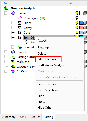
Edit a previously defined split direction. When you edit a direction, the faces that belong to this direction are automatically selected.
See QuickSplit Operation.
Notes:
- When invokinginvoking this option by right-clicking on a face that is attached to a QuickSplit direction:
-
- If a single face is selected or multiple faces from the same direction are selected, the Edit Split Direction option is available in the popup menu.
- If multiple faces from different directions are selected, the Edit Split Direction option is disabled (not available) in the popup menu.
- Accessing the edit direction menu does not require activating the work part.
- While in the 'edit direction' stage, you can invokeinvoke the Edit Split Direction option on another direction.
General Interaction
The Edit Split Direction Feature Guide is displayed.
|
|
|
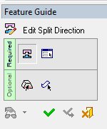
Required Step 1 
Select the QuickSplit set to edit (single selection, one face).
Note: This step will be skipped if you navigated to the feature using Edit Split Direction from the Parting Tree, because set to work on was defined by your selection in the tree.
Required Step 2 
Edit the split direction. The feature recognizes how the split was originally made, using either visual analysis or solid analysis, and displays the appropriate options. When using the Visual (Surface-Based) Analysis, only the option One Direction is available.
- Click OK or Cancel, you will be returned to the main QuickSplit menus.
- Click Apply, the settings are applied, all faces are deselected, and the Feature Guide moves back to Step 1 so you can select a different QuickSplit set.
Optional Step 1 
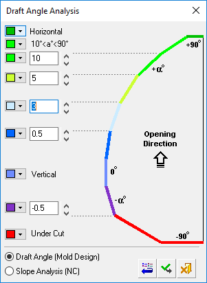
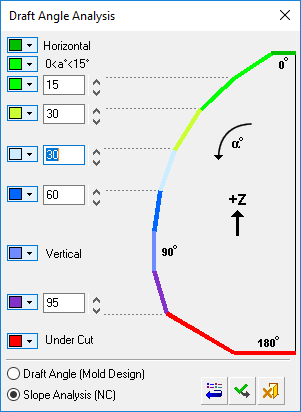
Perform the Draft Angle Analysis. Display the Draft Angle Analysis color dialog and show the draft angle when moving the cursor over the faces selected for assignment. A toggle option is available in the draft angle analysis that enables you to take into consideration the attached parting surface.
|
New Direction optional step 1 parameters: |
Edit Direction optional step 1 parameters; the toggle option Ignore Attached Parting Surfaces / Include Attached Parting Surfaces is displayed: |
|
|
|
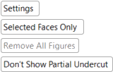
The following toggle options are displayed:
|
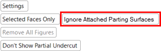
Settings |
Display the Draft Angle Analysis dialogDraft Angle Analysis dialog. See below for additional information. |
||||
|
Selected Faces Only / |
Using the toggle option, decide which faces go into the draft angle analysis.
|
||||
|
Ignore Attached Parting Surfaces/Include Attached Parting Surfaces |
When applying the draft angle analysis, either ignore the attached parting surfaces (default) or apply the draft angle analysis to parting surfaces attached to the relevant opening direction. After completing the parting surface, you can check for possible undercuts of a parting surface by invoking the Edit Direction function and using the draft analysis option.
|
||||
|
Remove All Figures |
Click the Remove All Figures button to remove all the angle value labels from the display. This option is grayed out if there are no angle value labels in the display. |
||||
|
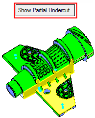
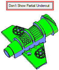
Show Partial Undercut / |
This is a toggle option Show Partial Undercut / Don't Show Partial Undercut to enable you to show partial undercuts for analysis, or not to show them. For all system calculations, there is a correlation between the required accuracy level and the duration of the calculations; setting a higher accuracy level will extend the calculation time.
|
Optional Step 2 
Manually define faces to always be included in the parting direction.
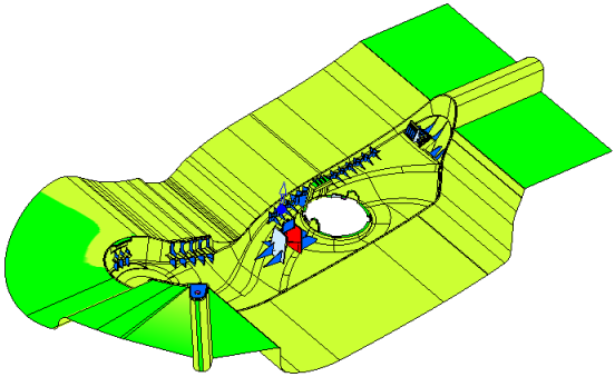
After an analysis, faces with a partial undercut are colored YELLOW and are not normally added to the selection list of faces to be included in the parting direction. However, by using this optional step, these faces can be added manually by selecting them.
ExampleExample
If you do not want these (partial undercut) faces to be considered as undercut in the next analysis (when using the Edit Split Direction function only), use this optional step (Manually Defined Faces) to select the faces to always be included in the parting direction.
When entering this optional step, all faces that are selected in the required step are colored DARK GREEN (the color of entities selected in a previous step). The (partial undercut) yellow faces remain yellow. Faces that were previously marked in this optional step are marked as selected.
You can select or unselect any face; selected faces are always included in the parting direction. The following dropdown list of options is displayed, enabling you to control which faces can be selected/unselected:
|
Select All Faces |
All faces can be selected or unselected. |
|
Select Yellow Faces Only |
Only the yellow faces (those marked as partial undercut in a previous analysis) can be selected or unselected. This is the default option. |
| Select Unassigned Faces Only |
Only the unassigned faces can be selected or unselected. |
A selected face goes into the parting direction in a forced mode; it stays there even if you later click the Clear Selection button. This face cannot be attached to other parting surfaces; this means that the status of this face is more powerful than the All Faces option (see the New Direction > Analyze By Solid & PS Part and Visual Analysis options) in another parting direction analysis. If you select a face that was marked as "manually defined" in another opening direction, the old attribute is removed and it will be marked as manually defined for the current direction. If you attach the face to another opening direction manually, the attribute is removed.
If the opening direction is deleted, the "manually added" attribute is also deleted.
Note: All manually added faces are added to the manually assigned faces list. This includes faces added using this optional step and also includes faces that are manually attached (using the Attach option) or manually picked and assigned in QuickSplit.
Manually added faces can be cleared (unselected) by using the Clear Manually Added Faces or Clear All Manually Added Faces popup options from the Parting Tree (see below for details).
Clearing Manually Added Faces
If you have manually defined (added) faces to be included in the parting direction, whether or not by using the Manually Defined Faces optional step (of the New Direction function - see above), these manually added faces can be cleared (unselected) by using the Clear Manually Added Faces or Clear All Manually Added Faces popup options from the Parting Tree.
|
Clear Manually Added Faces |
This option is displayed in the popup menu of an split opening direction (in the Parting Tree), and it removes the "manually added" attribute from those faces and unselects them. The relevant faces are highlighted (these are the faces that are about to be cleared) and a message is displayed requiring confirmation if this operation. |
|
Clear All Manually Added Faces |
This option is displayed in the popup menu of a work part (in the Parting Tree) and it clears the manually defined faces of all parting directions of that part. |
Function Completion
Press OK ![]() or Apply
or Apply ![]() in the Feature Guide to complete the function. The selected faces are assigned to the new direction.
in the Feature Guide to complete the function. The selected faces are assigned to the new direction.
The split information is displayed in the Parting Tree.
In the Assembly environment the following actions occur:
A new split direction set is created under the activated part. The color of the new direction is different from the color of all the other split directions in the entire assembly.
If the part did not have a split direction before, it is now created and the part appears in the Parting Tree.
The name of the set is Split-XX where XX is the consecutive number of the existing directions. By default, these names are defined in the Preferences. To locally rename a split direction, right-click on a split direction in the Parting Tree and select Rename from the popup menuRename from the popup menu.
No QuickSplit analysis is run and the faces have to be manually attached to the set.
See also
|