|
|
Manufacturing Attributes  : Options and Results

Access: Open this function from one of the following locations:
-
Select the
Manufacturing
Attributes icon from the Hole and Threads
toolbar. -
Select Tools > Main Tools > Manufacturing Attributes from the menu bar.
Attach machining and tolerance information to holes. This enables you to apply and customize several types of manufacturing processes as well as diameter and depth tolerances.
The Manufacturing Attributes attached to holes (machining and tolerance information) is shown in Drafting, when defining the Label of Holes and the Table of Holes (where all the Manufacturing Attributes are displayed), and in NC Automated Drill procedures to help define the drill sequence.
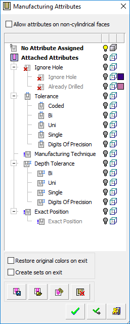
The Manufacturing Attributes dialog is displayed.
|
|
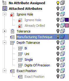
The dialog contains the following sections: No Attributes Assigned Attached Attributes a. Ignore Hole b. Tolerance c. Depth Tolerance d. Exact Position Notes:
|
Manufacturing attributes can be set manually or by loading a predefined table of attributes. Holes can be attached to these attributes manually or automatically.
Add a Manufacturing Attribute
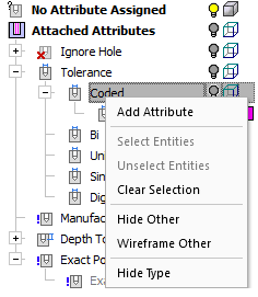
Right-click an attribute in the Attached Attributes section of the Manufacturing Attributes dialog and select Add Attribute from the popup menu. See the Attribute Types below.
Example:Example:
A dialog relevant to the selected attribute is displayed, enabling you to manually set attributes that can later be attached to faces.
Set the attribute color  and visibility
  /
/ as required.
Attach an attribute to a face
Pick the required face.
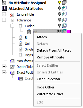
Right-click the relevant Manufacturing Attribute (added as described above) and select Attach from the popup menu.
Example:Example:
Dialog Structure
The Manufacturing Attributes dialog consists of:
Attribute Settings
The Manufacturing Attributes dialog contains the following sections:
|
No Attributes Assigned |
This section of the dialog includes all faces of the model (or assembly) that do not have a hole attribute attached to them. |
||||||||||||
|
This section of the dialog includes all faces of the model (or assembly) that have a hole attribute attached to them. The following sub-sections appear here (listed in order of appearance) with each sub-section containing rows (types) of attributes:
Faces attached to these rows receive the color of the row. You can control the visibility and colors in this section. See Attribute Types and Popup Menus for additional information. |
Notes:
-
All rows (types) in all sections that are empty (no face is attached) are displayed as disabled (grayed out) on the tree (so that you can easily distinguish between empty and "attached" rows).
-
If a face is attached to a certain type (row) and this face was already attached to another type, it will be unattached from the other type; a face is "attached" only to one type within the same section.
The rows (attributes types) that can be defined in the Attached Attributes section of the dialog are listed below in order of appearance.
Right-click popup operations are available for rows and their sub-rows in the dialog table and also in the graphics area. The contents of the displayed popup menu depends on the where the operation was invoked. The Add Attribute popup option enables you to manually set attributes that can later be attached to faces; where relevant, the appropriate Add Attribute dialogs are shown below.
|
Ignore Hole |
Faces attached to this attribute are ignored in subsequent operations; for example, to ignore holes in plates that already contain holes in various locations or for catalog parts that already contain holes in various areas, or to ignore holes in the Table of Holes in Drafting or when drilling in an NC file. This attribute type appears in the Ignore Hole section of the Manufacturing Attributes tree. |
||||||||||||
|
Already Drilled |
Faces attached to this attribute are marked as already drilled for subsequent operations. This attribute type appears in the Ignore Hole section of the Manufacturing Attributes tree. |
||||||||||||
|
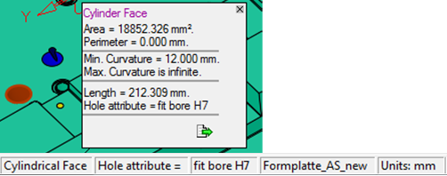
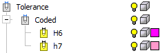
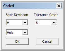
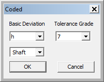
This attribute type includes hole diameter tolerances (H6, H7, etc.).
This attribute type appears in the Tolerance section of the Manufacturing Attributes tree. |
|||||||||||||
|
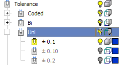
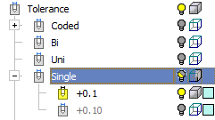
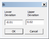
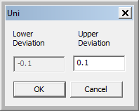
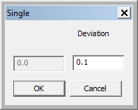
Set the Bilateral, Unilateral, and Single Tolerance deviation attribute types. These attribute types appear in the dialog table as follows:
For these attribute types, the following applies:
The following Add Attribute popup option dialogs are displayed:
These attribute types appear in the Tolerance and Depth Tolerance sections of the Manufacturing Attributes tree. |
|||||||||||||
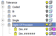
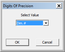
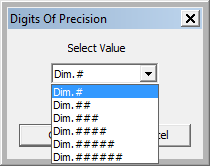
|
Set the Digits of Precision attribute type.
This attribute type appears in the Tolerance and Depth Tolerance sections of the Manufacturing Attributes tree. |
|||||||||||||
|
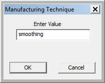
Manufacturing Technique |
This section enables the entry of various Manufacturing Technique attribute types.
Notes:
|
||||||||||||

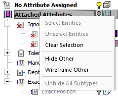
Right-click popup operations are available for rows and their sub-rows in the dialog table and also in the graphics area. The contents of the displayed popup menu depends on the where the operation was invoked.
|
Dialog table popup menu: |
Dialog table popup menu: |
Graphics area popup menu: |
|
|
|
|
|
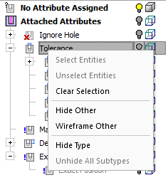
Dialog table popup menu: |
Dialog table popup menu: |
|
|
|
|
Popup Options
|
Add Attribute |
Add an attribute type. A dialog is displayed enabling you to enter the attribute data. See the Attribute Types above. |
|
Attach |
Attach an attribute to a selected face. |
|
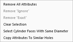
Clear Selection |
Clear all selected entities. |
|
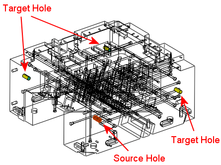
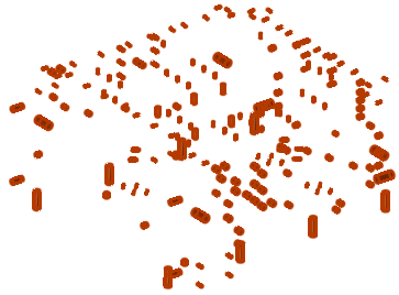
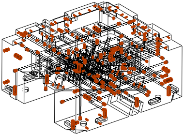
Copy Attributes to Similar Holes |
Copy the attributes of a selected cylindrical face to similar holes. The part is displayed in wireframe with the source and target holes highlighted. A confirmation message is displayed for this action.
|
|
Detach |
Detach an attribute from a selected face. |
|
Detach from All Faces |
Detach attributes from all faces. |
|
Edit |
Edit a defined attribute. |
|
Hide Other |
Hide all other items except for the selected entities.
|
|
Hide Type |
Hide the attribute type from the dialog table sections. |
|
Remove All Attributes |
Remove all attributes from the selected faces. |
|
Remove Attribute |
Remove (delete) the attribute. |
|
Remove "Exact" |
Remove the Exact Position attribute from selected faces. |
|
Remove "Ignore" |
Remove the Ignore Hole attribute from selected faces. |
|
Select Cylinder Faces with Similar Diameter |
Select all other cylindrical faces with a similar diameter to a selected cylindrical face. |
|
Select Entities |
Select the entities that have the attached attribute. |
|
Unhide All Subtypes |
Show any attribute types hidden in the dialog table sections. |
|
Unselect Entities |
Unselect any selected entities. |
|
Wireframe Other |
Display all other items in wireframe, except for the selected entities.
|
Parameters
The Manufacturing Attributes dialog contains the following parameters:
|
Allow attributes on non-cylindrical faces |
This enables you to set attributes on non-cylindrical faces. When the checkbox is OFF, attributes can only be set to cylindrical faces. This is the default option. When the checkbox is ON, attributes can be set to all types of faces. The Auto attach by color operation (see below) works according to this checkbox setting: OFF = Only cylindrical faces will be automatically attached. |
||
|
Restore original colors on exit |
This enables you to control the color of faces with hole attributes, after exiting the function using the OK button. When the checkbox is OFF, the faces will get the same color as shown in the Manufacturing Attributes dialog. When the checkbox is ON, the original color of the faces (as they were before invoking the function) will be restored. This is the default option. |
||
|
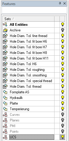
Create sets on exit |
This enables you to create or update Sets with attribute data when exiting the Manufacturing Attributes dialog using the OK or Apply buttons. When the checkbox is OFF, no sets are created. This is the default option. When the checkbox is ON, sets are created as detailed below:
|
Buttons
The Manufacturing Attributes dialog contains the following buttons:
|
|
Save to File: Save the attributes to HAT (Hole Attribute Template) file. The following information is saved:
By default, the HAT file is saved to the folder: ...\ProgramData\Cimatron\Cimatron\2026.0\Data\templates\HoleAttributes |
|
|
Load from File: Load ALL attributes and defaults from the saved HAT file. Existing rows that are empty (nothing attached to them) will be removed if they do not exist in the "saved" template. Existing rows that are NOT empty (some faces attached to them) will NOT be removed if they do not exist in the "saved" template. |
|
|
Auto Attach by Color: This enables color coding for holes. This operation automatically finds a cylindrical face with a certain color but without hole attributes, and automatically attaches attributes to these faces according to those defined in the dialog. Faces that already have hole attributes do not receive the new (auto attached) attributes. |
|
|
Clear All Attributes: Clear all attributes from the dialog and also all attributes from faces. A warning message is displayed required user confirmation of this action. |
|
The following approval options are available:
|
|
|
|
OK: Accept the changes, perform the operation, and close the current dialog/task. |
|
|
Apply: Accept the changes, perform the operation, and keep the current dialog/task open. |
|
|
Cancel: Cancel all changes and close the dialog/task without saving the settings. |


|