|
|
C
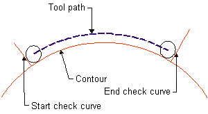
A curve used to mark the end of an open contour. Either this curve or its logical extension must intersect the contour.

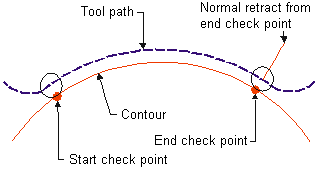
A point that marks the end of an open contour.

A check surface is used to marks the end of milling limits. The intersection between the check and part surface defines the milling boundary.
The Z value at a safe height above the material where the cutter can move without touching the part. The default value is equal to the Clearance Plane value.
Connection RadiusConnection Radius
For high speed cutting connections between passes, this is the radius of the arcs used to connect between passes. See also Connection Type.
Connection TypeConnection Type
Certain parameters allow you to set high speed cutting connections between passes, for:
Contour Approach / RetractContour Approach / Retract
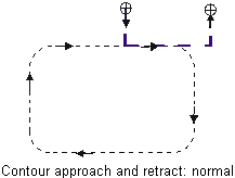
Normal: The cutter will approach / retract normal to the contour.

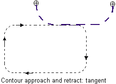
Tangent: The cutter will approach / retract through a 90° arc that is tangent to the contour.

These parameters are set in the Approach & Retract section of the Procedure Parameter Table.
Distance beyond the contour that will remain after machining.
Contour Offset (Rough)Contour Offset (Rough)
Additional offset (beyond the Part or Check Surface Offset) that will remain after rough machining.
(This parameter is set in the Offset & Tolerance section of the Procedure Parameter Table.)
Select from the list of coolants: Flood, Mist, Through, or Air. Select Off for no cooling.
Note: Corner Milling options vary depending on the procedure. Volume Milling, Spiral or Stock Spiral Cutting, 3D.
Cut DirectionCut Direction (Corner Milling)
Note: Corner Milling options vary depending on the procedure. Volume Milling, Spiral or Stock Spiral Cutting, 3D.
Cutter Location (Offset)
The meaning of this parameter depends on the type of procedure using it.
|