|
|
Local Operations  > Ruled Surface
Access:
-
For Technology, choose Local Operations as the main selection, and Ruled Surface as the subselection. Choose 3x, 4x, or 5x, depending on the type of toolpath.
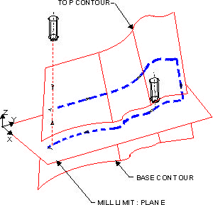
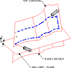
Create a sequence of linked ruled surfaces, defined by two contours, and create tool motions for machining them following their parametric curves using 3, 4 or 5-axis machining.
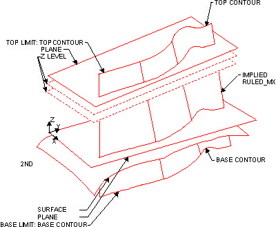
The ruled surface is defined by connecting the endpoints (contour break points) of the curves of the two contours (open or closed) by straight line segments.
Illustration of Local Operations - Ruled SurfaceIllustration of Local Operations - Ruled Surface
|
Ruled_MX |
|
|
Ruled_MX |
|
|
Ruled_MX |
|
 Hints and tips for milling Linked Ruled Surfaces
Creating this procedure
See Creating a Procedure for a general explanation.
-
For Technology, choose Local Operations as the main selection, and Ruled Surface as the subselection. Choose 3X, 4X, or 5X, depending on the type of toolpath.
-
Choose the appropriate cutter.
-
Define the contour type (open or closed), top and base contours and the top and base limits.
-
The top limit can be the top contour, a plane or a Z level.
-
The bottom limit can be the base contour, a plane or a surface.
See the illustration above.
-
-
Define the following Motion Parameters:
-
Define the Machine Parameters.
-
When finished, you can choose from the following Work Mode Dialog buttons:
(These options are also available on the Procedure popup submenu.)
|


