|
|
Cutters & Holders Parameters  : Motion Parameters

Access: Open this function from one of the following locations:
The Cutters and Holders dialog (or the minimized version - the Select Only Mode):
-
When not editing or creating a procedure, select NC-Process > Cutters > Cutters from the menu bar or select Cutters
in the NC Guide Toolbar. -
While editing or creating a procedure, use one of the following methods (in both methods, the Select Only Mode is displayed):
-
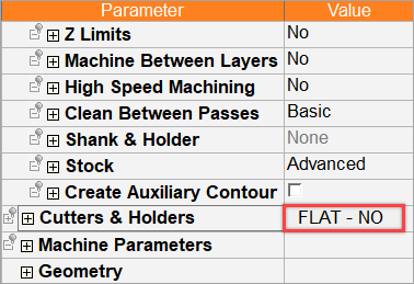
In the Advanced Mode, click on the cutter name in the Procedure Parameter Table.
-
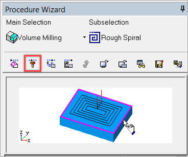
In the Wizard Mode, select the cutter button.
-
-
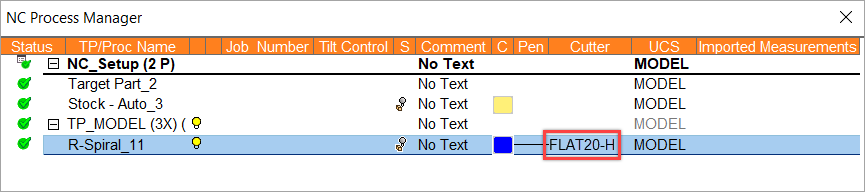
In the Process Manager, click on the cutter name in the procedure row (in this case, the Select Only Mode is displayed).
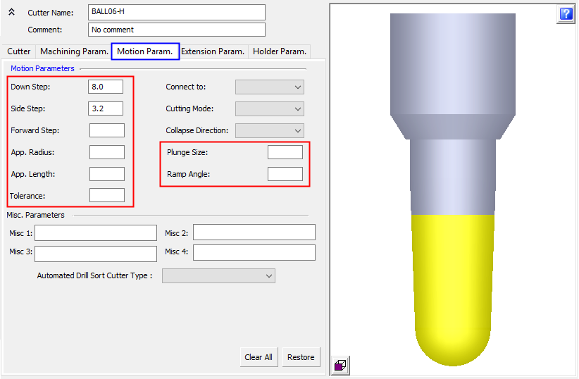
This topic discusses how to set default Motion Parameters for a cutter.
In the image below, parameter fields in the red highlighted areas will accept expressions such as 7/8, 5/25.4. Relations to other parameters (such as tldi/2) cannot be defined (see Miscellaneous Parameters below).
For a parameter description, click on a parameter in the dialog image below.
To display additional parameters, click the relevant tab in the dialog image below.
For more information, see Miscellaneous Parameters and Automated Drill Sort Cutter Type below.
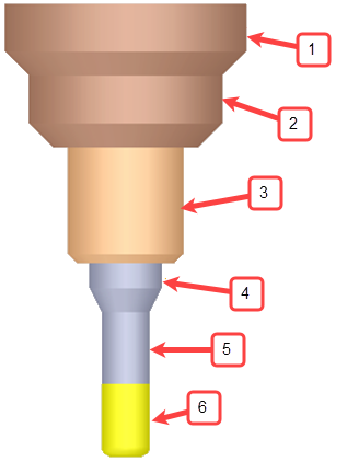
|
An example cutter with a holder and multiple spindles. |
|
In this topic
See also
|
|
Miscellaneous Parameters
The Miscellaneous Parameters are comment text fields of up to 20 characters. These parameters appear in the Column Chooser (they can be filtered and sorted by those columns) and are output to the Post and to the NC Report.
|
Clear All |
Clear all the parameter values in this tab. |
|
Restore |
Restore all the parameters in the tab to their previous values. |
While editing parameter values, the following system checks are conducted and associated prompts are displayed to ensure that the correct parameter values are entered:
-
When cutter parameter values are changed, the system checks whether the cutter(s) is used in a procedure(s) and whether the changes influence the procedure execution. If both conditions occur, a message is displayed informing you that all procedures that use this cutter(s) may be suspended if you approve the changes.
-
When editing a parameter value, any other parameter that may be affected by the edit is displayed with an orange background color.
-
Invalid parameter values are displayed in RED and signify that these values should be changed. If the Apply button is pressed while invalid parameter values appear in the dialog, a message is displayed with additional information regarding these parameters.
Example of invalid parameters displayed in REDExample of invalid parameters displayed in RED.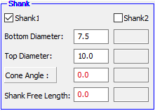
Automated Drill Sort Cutter Type
The Automated Drill Sort Cutter Type parameter is used to define to which cutter type (cutter family) the cutter belongs. The dropdown list of the various cutter types is defined in the General NC Preferences. This option is part of the process to enable user sorting of cutters in the Automated Drill procedure.
This parameter is displayed only if the Special Automated Drill Sort checkbox is ON in the General NC Preferences.
Automated Drill User-Defined Cutter Sorting
The process to enable the automatic sorting of cutters inside an NC Automated Drill procedure, is as follows:
Define the cutter types (cutter families). In the General NC preferences, set the Special Sort for AutoDrill checkbox to ON and define the various cutter types.
Define the sort order of the cutter types. In Special Automated Drill Sort preferences, set the Use Special Sort checkbox to ON, add the cutter type (defined in #1) and define the sort order within the cutter type.
For each cutter in the cutter table, define to which cutter type it belongs. In the Motion Param. tab and the Cycle Param. tab of the Cutters & Holders dialog, select the cutter type from the Automated Drill Sort Cutter Type dropdown list. This dropdown list is only displayed if the Use Special Sort checkbox (#2) is set to ON.
In the Automated Drill procedure Drill Parameters table, set the Process Optimization parameter to the By Cutters by User Order option. This option is only available if the Use Special Sort checkbox (#2) is set to ON
In the Automatic Drill Cutter List dialog, the value in the column Cutter Type column is as defined for each cutter in the Cutters & Holders dialog (#3). The Cutter Type column is only displayed if the Process Optimization parameter is set to the By Cutters by User Order option (#4).
Note: Cutters used by the Automated Drill procedure that have not been defined a cutter type (#3), or have a value that does not appear in the Special Sort for AutoDrill list (#1), will assume the lowest priority in the sort order.
Using the Motion parameters within a procedure
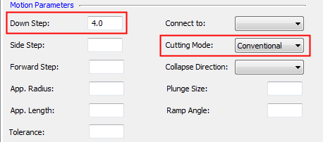
In this example, the following Motion parameters have been defined for a cutter.
|
In the Cutters and Holders dialog: |
Within the NC procedure, the corresponding parameters have already been defined with different values. |
|
|
|
Using the cutter-specific motion parameters
Right-click on the Parameter section of the NC procedure to display the popup menu and select the appropriate option.
For example, select the option Set motion params only.
The relevant Motion Parameters in the NC procedure are set according to the values in the Motion Parameter tab of the Cutters & Holders dialog. They are displayed below, on the left, as changed values.
|
New Values |
Original Values |
|
|
|
Note: When selecting the option Set motion params only (by right-clicking on the Parameter section of the NC procedure), the following behavior occurs:
|
Motion Parameter tab of the Cutters & Holders dialog |
|
Motion Parameters in the NC procedure |
|
Ramp Angle = 90 |
|
Entry Mode = Drilling Ramp Angle = 90 degrees
|
|
Ramp Angle = 0 |
|
Entry Mode = No Plunging Ramp Angle = 0 degrees
|
|
Ramp Angle = < any angle other than 90 or 0> |
Entry Mode = As selected Ramp Angle = < value from Cutters & Holders dialog> |
|
|
Cutting Mode = Mixed |
Cutting Mode = Mixed or Mixed+Climb Final Pass (if available)
|
|
|
Cutting Mode = Climb |
Cutting Mode = Climb |
|
|
Cutting Mode = Conventional |
Cutting Mode = Conventional |
Ramping is a tool entry method whereby the tool enters the part by gradually increasing in depth, preventing any shock loading on the tool to avoid poor tool life or premature tool failure. The angle of entry is determined by a defined ramp angle.
|