|
|
Load Work Parts  : Options and Results

Access: Open this function from one of the following locations:
First activate the parting
assembly in the Parting
tree.
Example:
Example:
-
Select Parting > Layout Tools > Load Work Parts from the menu bar.
-
Select Parting Layout Tools > Load Work Parts from the Mold Design Guide Toolbar or Parting Guide Toolbar.
Import or add a work part to the assembly and position the work part onto the UCSs in the Layout Part. With this function, you can create a new work part from a master part file or load an existing work part.
The results of adding a work part can be viewed in the changed tree structure.
Notes:
-
This option is only available if a layout part has already been created.
-
Any UCS in the Layout Part will be considered a Layout UCS. However, note that using a UCS whose Z direction is not aligned with the mold's Z direction may cause undesired results in the QuickSplit simulation of parting surfaces.
Required Step 1 
This step allows you to load a master part file or an existing work part file and set their parameters.
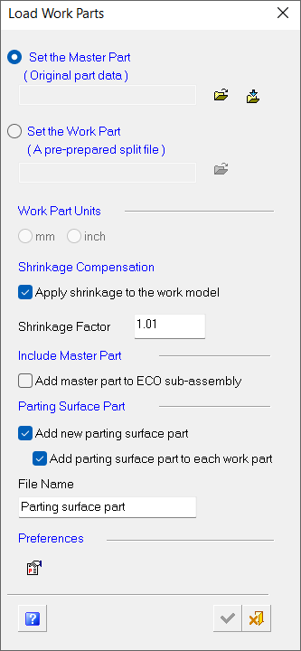
The Load Work Parts wizard is displayed.
|
|
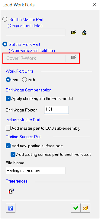
The wizard contains information regarding the master part file/work part file (see Parameters below for a complete description of the wizard's available options). You can either define a master part file (from which a work file is created) or directly define a work part file (without a master file). The steps associated with this function are as follows: Load a master part file by selecting Set the Master Part in the wizard or load an existing work part file by selecting Set the Work Part. Define the units of measurement for the file. Note that if you have defined a work part file, the units of measurement (Work Part Units) are grayed out and will be the unit of measurement of the work part file. Select the Apply shrinkage to the work model checkbox in the Shrinkage Compensation section and enter a value for Shrinkage Factor. Note that if you have defined a work part file, the Shrinkage Compensation parameters are grayed out and will be those of the work part file. In the Include Master Part section, select the Add master part to ECO sub-assembly checkbox if required. In the Parting Surface Part section, select the Add new parting surface part checkbox and/or Add parting surface part to each work part checkbox if required. Define parameters in the Preferences Editor Click
|
Parameters
|
Set the Master Part |
This option allows you to browse After selecting a master part, the system will automatically name the work part. The work part file name is derived from the name of the master part file with the suffix, -Work, added to the file name. You can change the file name, however, the suffix -Work will remain. This suffix is defined in Preferences. When selecting the master part, you have two choices:
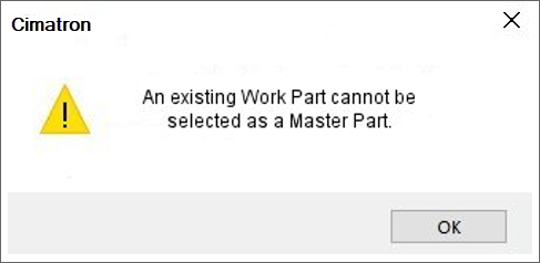
If you attempt to load a work part file instead of a master part file using this option, the following message will appear:
|
||||
|
Set the Work Part |
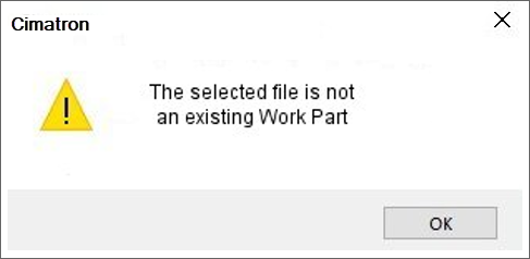
This option allows you to browse If you attempt to load a file other than a work part file, the following message will appear:
|
||||
|
Work Part Units |
This option designates the units of measurement – millimeters (mm) or inches (inch). Note that if you have defined a work part file, the units of measurement (mm and inch) are grayed out since the file inherits the unit of measurement of the selected work part file. |
||||
|
Shrinkage Compensation |
Use this option to increase or decrease the volume of an object(s) or the size of a face or sketch to produce mold shrinkage. You can also apply shrinkage parameters to one or more objects, open or closed.
|
||||
|
Include Master Part |
When this checkbox is ON (selected), a new sub-assembly (ECO) is opened under the main parting assembly and a Layout UCS is placed there – a copy of the master file used by the work file. (The copied master file will be used later for compare operations). |
||||
|
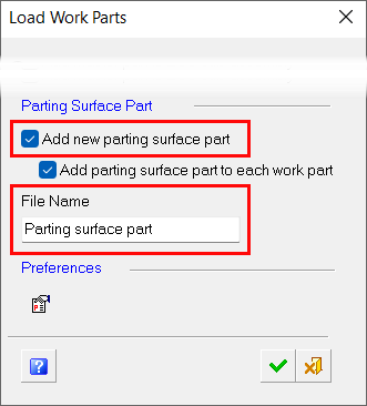
Parting Surface Part |
|
||||
|
Preferences |
Access Preferences to customize various Cimatron settings. |
||||
|
Help |
Open the Cimatron Help File to the Load Work Parts topic. |
Defining a Master Part File
A master part file is loaded if a work part file has not already been created. Use this method to define the master part file and create the work part file.
Load a master part file by selecting Set the Master Part in the Load Work Parts wizard. Use one of the following options to open/import a master part file:
-
Open File
 : Open an Cimatron file from the Cimatron Explorer.
 -
Import File
 : Import an external file (PFM, IGES, SAT, etc.)
Note: The work part file name is derived from the name of the master part file with the suffix, -Work, added to the file name. You can change the file name, however, the suffix -Work will remain. This suffix is defined in Preferences.
Defining a Work Part File
If a work file already exists, the part has already been split.
Load a work part file by selecting Set the Work Part in the Load Work Parts dialog and using Open File ![]() .
.
Note: If a work file is loaded, the Work Part Units and Shrinkage Compensation options in the Load Work Parts wizard are grayed out and the parameter values will be those of the work file.
Required Step 2 
Position the work parts onto the UCSs within the layout part.
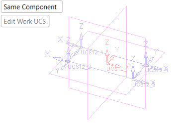
Set the Same Component / Different Component options if required.
PickPick the UCS(s) onto which to position the work part.
Note: Layout UCSs are the only UCSs you can pick while placing work parts.
|
The layout UCSs are displayed in BLUE. |
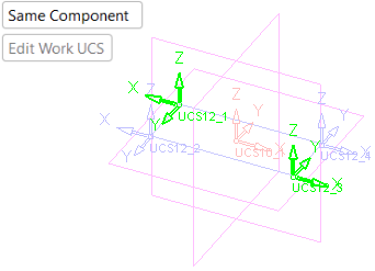
For clarity, in the image below the Layout UCSs to be picked in this example are highlighted in GREEN. |
|
|
|
After picking a Layout UCS, the following occurs:
-
A copy of the Layout UCS is created under the parting sub-assembly.
-
The Work CS is created. The default location of the Work CS in the center of the geometry.
A connect operation is carried out between these two new UCSs (the Work CS and the UCS created as a copy of the Layout UCS).
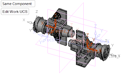
Select Edit Work UCS, if required, to relocate the Work UCS to another position on the work part. As the Work UCS is connected to the picked UCS, this will reposition the work part on the layout part.
If this is the final result, press OK ![]() or Apply
or Apply ![]() in the Feature Guide to complete the function.
in the Feature Guide to complete the function.
Changes in the tree structure after adding a work part
Once a layout part is defined the following occurs:
-
A Layout part is created in the Assembly Tree.
-
A Parting tab is created that contains the Parting Tree, which also contains the Layout part.
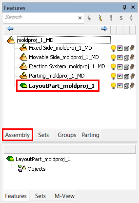
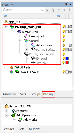
The tree structure before a work part is addedThe tree structure before a work part is added
|
The Assembly Tree showing the Parting sub-assembly and the Layout part. The latter is created when a Layout part is defined. Note that, when created in the Mold Project Wizard, the Layout part is activated. |
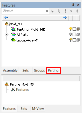
The Parting Tree. The Parting tab allows full control over the parting process, enabling you to activate various parts and control the hide/show status of different Parting sets. |
|
|
|
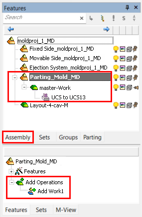
The tree structure after one work part is addedThe tree structure after one work part is added
|
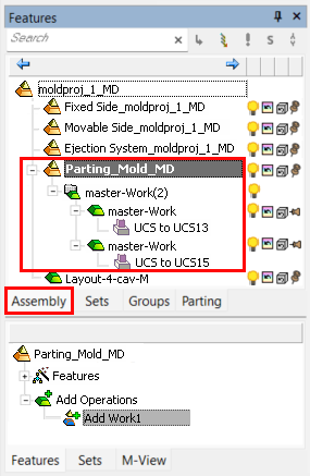
The Assembly Tree shows the work part after it has been loaded. The Feature Tree shows the new Add Work Operations. |
The Parting Tree shows the work part after it has been loaded. |
|
|
|
The tree structure after the 2 work parts (in the example above) are added:
|
The Assembly Tree shows the 2 work parts after they have been loaded. The Feature Tree shows the new Add Work Operations. |
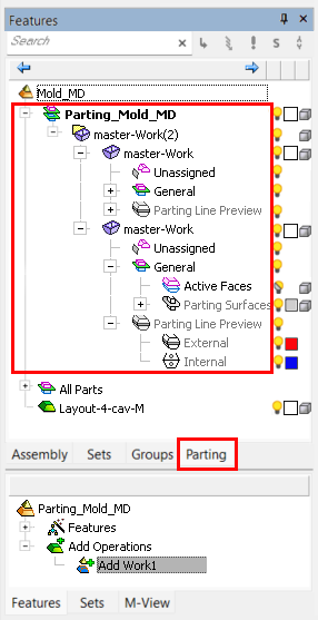
The Parting Tree shows the 2 work parts after they have been loaded. |
|
|
|
|