|
|
Remachine  > Guided Cleanup
  / Multi Axes Guided Cleanup
![]()
![]()
Access:
-
For Technology, choose Remachine as the main selection, and Guided Cleanup or Multi Axis Guided Cleanup as the subselection.
Identifies and cleans unmachined areas that remain after previous machining operations.
The Guided Cleanup and Multi Axes Guided Cleanup procedures enable you control and manage the re-machining process resulting in faster, safer and more efficient re-machining programing.
These procedures are best utilized for large components where it is required to approach from different orientations in order to complete the re-machine operation. For example, in large cavities for automotive parts, it is extremely difficult to find a single direction for all Cleanup operations. The guided cleanup procedures enable you to define different directions for each cleanup region.
|
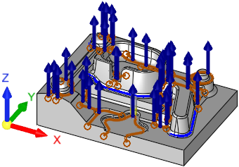
Guided Cleanup: Segments are milled from the Z direction. |
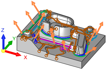
Multi Axis Guided Cleanup: Segments are milled by the vector direction of each curve. |
|
|
|
The Guided Cleanup and Multi Axes Guided Cleanup procedures use the Remachine Segments function, to identify pencil curve segments. The identified segments can be manipulated in various ways, to ensure smooth and efficient motions.
The milling order for both procedures is by direction. All segments of a specific direction are milled before the next direction is started. Within each direction, the milling order is as defined in the procedure.
Both procedures consist of two main stages:
This function finds all unmachined regions (segments) for a previously used reference cutter. All data is displayed in the graphics window and controlled via the Remachine Segments Table.
When the Remachine Segments Table is invoked from the menu toolbar, these segments can be edited as required. They can be deleted, merged, split, trimmed and given a direction based on future machining requirements.
When the Remachine Segments Table is invoked from within a procedure (the NC Parameter table grid > Geometry > Remachine Segments option), editing operations on these segments are not available.
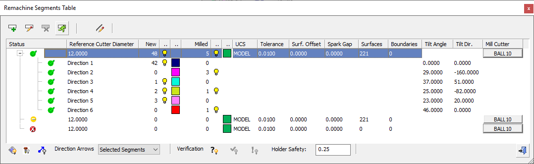
This table is the user interface environment to manage, handle and create the various cleanup segments. The segments are an input for the Guided Cleanup and Multi Axes Guided Cleanup procedures.
-
The procedures:
These procedures use and machine pre-calculated cleanup segments.
|
Guided Cleanup |
Identifies and cleans unmachined areas that remain after previous machining
operations.
The Guided Cleanup procedure
ignores the direction vectors from the Remachine
Segments Table. Each segment or group of segments are milled from
the Z direction. In this case a Cleanup procedure is created for each
direction. |
|
Multi Axis Guided Cleanup |
Identifies and cleans unmachined areas that remain after previous machining
operations.
The Multi Axes Guided Cleanup
procedure uses the direction vectors from the Remachine
Segments Table. This procedure tilts all motions created by a pencil
curve to the vector direction of that curve. Each segment or group of
segments are milled by the direction associated with it, making it a 3+2
Axis procedure. The angle between the direction of a curve selected in Multi Axis Guided Cleanup and the UCS of the procedure cannot exceed 90°. This is checked when saving or calculating the procedure. |
 Hints and tips for Cleanup procedures
Create this procedure
See Creating a Procedure for a general explanation.
Notes:
-
When a previous procedure leaves material, Cleanup takes this remaining material as the stock.
-
If there is no remaining material from a previous procedure (the current procedure is either a single procedure or has no connection with the previous procedure), Cleanup uses the remaining material that remains from the previous tool of this procedure.
-
For Technology, choose Remachine as the main selection, and Guided Cleanup or Multi Axis Guided Cleanup as the subselection.
-
Choose the appropriate cutter.
Note: The Minimum Clear Length calculation is available for this function.
-
Define the geometry and, only if necessary, define the boundary area.
-
Define the following Motion Parameters:
-
Boundary Settings (appears in Guided Cleanup not in Multi Axes Guided Cleanup)
-
Define the Machine Parameters.
-
When finished, you can choose from the following Work Mode Dialog buttons:
(These options are also available on the Procedure popup submenu.)
|