|
|
Add Cooling Item With Channel  : Options and Results

Access: Open this function from one of the following locations:
-
Select Mold Design > Cooling > Add Cooling Item With Channel from the menu bar.
-
Select Cooling > Add Cooling Item With Channel from the Mold Design Guide Toolbar.
Add cooling items (plugs, nipples, baffles, and so on) from the catalog and create cooling channels for them.
The system automatically creates the suitable cooling channels according to the applied parameters.
For information regarding the catalog dimensions required to maximize the abilities of the Add Cooling Item With Channel function, see Catalog Building Rules: Baffle.
Required Step 1 
-
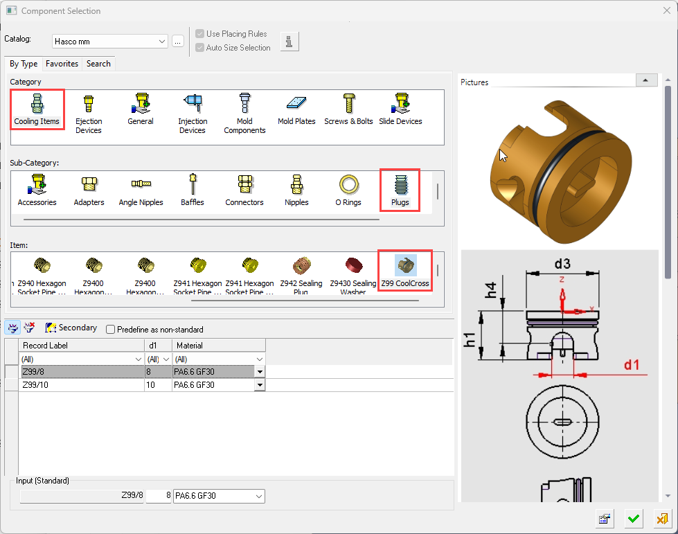
Select a cooling component from the catalog. The Component Selection dialog is displayed. See the Example Catalog Component Selection Process, below.
The Component Selection dialog is displayed with the appropriate catalog Category, Sub-Category and Item component types automatically selected. In the example dialog below, the Category = Cooling Items, Sub-Category = Nipples and Item = Extension nipple were automatically selected; change the selection, as required.
Example Catalog Component Selection ProcessExample Catalog Component Selection Process
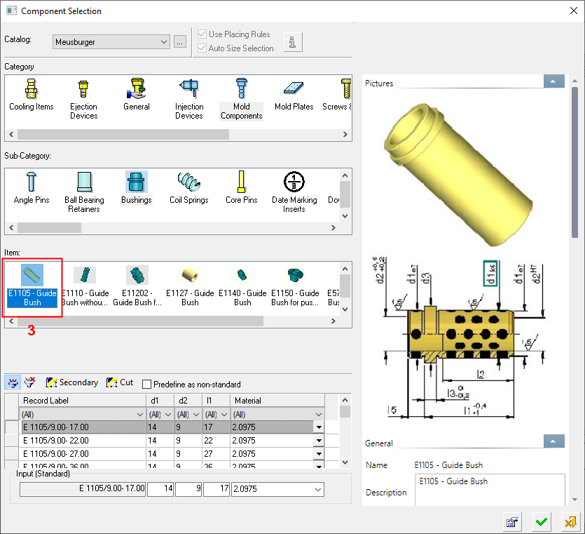
When selecting a catalog component, the Component Selection dialog is displayed with the appropriate Category component type automatically displayed (depending on the function invoked) and Sub-Category component types displayed for selection.
An example catalog component selection process is described as follows (in this case, for Mold Components):
The appropriate Category component type is automatically selected and the Sub-Category component types are displayed for selection.
The Item row of the dialog displays a small image of the actual components, which enables easy recognition of the items. Pick a component item from this row, select the required size record from the catalog table and then position the component on the assembly.
If required, perform the optional steps of this function.For more, see Component Selection.
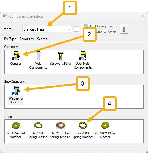
- Select the required catalog (1 in the image above).
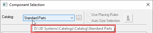
Hover over the displayed catalog name to display a tooltip showing the catalog location in your computer. The default catalog location can be set in the Cimatron Control Panel.
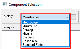
To change the catalog, either browse to the required catalog location , or select a catalog from the dropdown list; this list contains the last 10 catalogs used.
When a catalog is selected, the appropriate catalog Category and Sub-Category component types are automatically displayed (depending on the Catalog type). - Select the required Category and Sub-Category component types (for example, 2a and 2b in the image above). When you select a Category component, the appropriate Sub-Category components are automatically displayed.
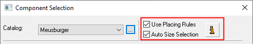
When you select a Sub-Category component type, if placing or size rules have been applied to this component, the Rule Information button and the Placing/Size Rules checkboxes become available for use, as shown below. These rules can be edited as required using the Rules Editor.
- Depending on the Sub-Category component selected, the appropriate Item components are then displayed. Select the required component item (for example, 3 in the image above).
When the component item is selected, the Catalog Table and Properties of the relevant component are displayed.
- Click the Properties buttonProperties button
 to hide the Properties and to expand the Catalog Table to the full width of the dialog.
 - Select the required record from the catalog table and click OKOK
 to select the catalog item or click CancelCancel
  to exit.
- Select the required catalog (1 in the image above).
Required Step 2 
-
Place the mold part using the Add Component positioning parameters. The following parameters are displayed:
The parameters are initially displayed as shown below. Toggle the parameters expand/collapse button
 /
/ to display the additional parameters.
-
Toggle the parameters expand/collapse button
/ to display the additional parameters.Place on Face
Select the required placing option from the dropdown list. Once a target entity (a face) has been selected, all the relevant positioning parameters are displayed. See the Add Component positioning parameters.
The Place on Face placing option is displayed by default.
No Interference
This is a dropdown list of options that determines the length of the cooling channel and added baffles, depending on the applied constraints. The following options are available (see the example images of these dropdown option descriptions, below):
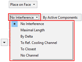
Examples of the dropdown options:Examples of the dropdown options:
No Interference:
Radial Offset=5
Tip Offset-7
No Interference:
Radial Offset=4
Tip Offset=7
Maximal Length:
Radial Offset=7
Tip Offset=7
By Delta:
Delta=54
To Ref. Cooling Channel: Extension=0 Radial Offset=7 Tip Offset=7 To Closest:
Radial Offset=8
Tip Offset=7
No Channel:
No Interference
The system calculates the maximum length of the cooling channel, avoiding interference of the Safety Offset (Radial Offset and Tip Offset - see below) with selected types of faces.
This is the default option.An additional parameter, a toggle option, is displayed that determines the selected types of faces where interference is to be avoided. The selected types of faces can either be faces that belong to parting sub-assembly components or to the active faces group. The following toggle options are available:
By Parting Sub-Assembly
The system extends the cooling channel's length to the first point where the Safety Offset intersects a parting sub-assembly's component.
If the system cannot find any parting sub-assembly component along the extend direction, it will look in higher assembly levels.
By Active Components
The system extends the cooling channel's length to the first point where the Safety Offset intersects an active face (split direction face).
If the system cannot find any active face along the extend direction, it will look in higher assembly levels.
This is the default option.Notes:
-
These toggle options appear for the No Interference and Maximal Length dropdown options, however, the results are different.
-
When creating the hole for the cooling items in a deeply nested sub-assembly, finding reference faces against which to define the length of the hole, may prove difficult if those faces reside in a higher nested sub-assembly. To solve this issue, the system looks for faces in higher level sub-assemblies when it can't find any in the current sub-assembly. This is relevant for the options No Interference and Maximal Length.
-
When creating the hole for the cooling items, the hole length values are rounded downwards to ensure there is no penetration or close proximity to walls as a result of rounding to the nearest value, which may be upwards. This is relevant for the options No Interference and Maximal Length.
-
If the Same Component toggle option is selected (Different Components / Same Component), the By Delta option is automatically selected and grayed out and all cooling item holes will be the same length as the shortest hole.
See the example images above.
Maximal Length
The system calculates the maximum length of the cooling channel by extending it (in the added part Z direction) until it reaches the first face belonging to selected types of faces.
An additional parameter, a toggle option, is displayed that determines the selected types of faces. The selected types of faces can either be faces that belong to parting sub-assembly components or to the active faces group. The following toggle options are available:
By Parting Sub-Assembly
The system extends the cooling channel's length to the first face where it intersects a parting sub-assembly's component. The length of each cooling hole is such that the tip of the Safety Offset (in effect, the top of the Tip Offset) will be at that point.
If the system cannot find any parting sub-assembly component along the extend direction, it will look in higher assembly levels.
By Active Components
The system extends the cooling channel's length to the first face where it intersects an active face (split direction face). The length of each cooling hole is such that the tip of the Safety Offset (in effect, the top of the Tip Offset) will be at that point.
If the system cannot find any active face along the extend direction, it will look in higher assembly levels.
This is the default option.Notes:
-
These toggle options appear for the No Interference and Maximal Length dropdown options, however, the results are different.
-
When creating the hole for the cooling items in a deeply nested sub-assembly, finding reference faces against which to define the length of the hole, may prove difficult if those faces reside in a higher nested sub-assembly. To solve this issue, the system looks for faces in higher level sub-assemblies when it can't find any in the current sub-assembly. This is relevant for the options No Interference and Maximal Length.
-
When creating the hole for the cooling items, the hole length values are rounded downwards to ensure there is no penetration or close proximity to walls as a result of rounding to the nearest value, which may be upwards. This is relevant for the options No Interference and Maximal Length.
-
If the Same Component toggle option is selected (Different Components / Same Component), the By Delta option is automatically selected and grayed out and all cooling item holes will be the same length as the shortest hole.
See the example images above.
By Delta
Set a delta value to determine the length of the cooling channel. A global or local delta values can be set.
To set a global delta value, enter the required value in the Delta parameter field displayed adjacent to the By Delta option.
To set a local delta value for each cooling item, pick the relevant item and set the delta value in the attached local parameter label.
See the example images above.
To Ref. Cooling Channel
Select an existing cooling channel(s) and make it the reference that will determine the length of the cooling item holes. Press <exit><exit> or the Esc key when finished.
An Extension parameter is displayed adjacent to the To Ref. Cooling Channel option. This extension parameter sets an additional length beyond the reference channel.
The
 button is also displayed adjacent to the To Ref. Cooling Channel option. This button enables the selection of cylindrical faces to select the reference cooling channels.
The selected reference channels and the direction of each cooling item is used to determine the length of the cooling item holes.
See the example images above.
To Closest
Extend the cooling object until it reaches the closest wall in the same part. The cooling object is extended full diameter and does not have a tip at the end.
See the example images above.
No Channel
Do not create a cooling channel. Add the cooling item without the cooling channel.
See the example images above.
Manual Analysis
This is a toggle option (Manual Analysis / Automatic Analysis) that determines when the system calculates the lengths of all cooling item holes. The following toggle options are available:
Manual Analysis
Calculate the lengths of all cooling item holes only when the adjacent Analyze button is pressed. This button is displayed when this toggle option is selected.
This is the default option.Automatic Analysis
Constantly calculate the lengths of all cooling item holes. In this mode, the length and interference of cooling item holes is recalculated whenever a cooling item is moved (or changes position using the delta and rotation optional stage) or whenever any other parameter is changed.
See the notes at the end of these parameter descriptions.
Recalculate Item Length
All Items are regenerated to display their true length relative to their CHL dimension. This parameter is only displayed if the selected item has a CHL dimension (Cooling Hole Length) defined in the catalog part.
Example:Example:Before the Recalculate:
After the Recalculate:
Notes:
-
You can create CHL dimensions in the catalog file, preferably assigned to a dummy entity (line) and renamed to CHL. This dimension is updated from the result of the calculation, and you can also use it in a formula.
Example:Example:
-
For additional information regarding the catalog dimensions required to maximize the abilities of the Add Cooling Item With Channel function, see Catalog Building Rules: Baffle.
All lengths are subject to the Hole Depth Increment set in the Preferences, except when using the By Delta option, above.
CHD
If the catalog part has a column called CHD (Cooling Hole Diameter), this value is retrieved from it. This parameter is used by the system to define the size of the cooling hole.
Note: For additional information regarding the catalog dimensions required to maximize the abilities of the Add Cooling Item With Channel function, see Catalog Building Rules: Baffle.
The default CHD value is set in the Preferences.
Drilled End
This is a dropdown list of options that enables you to define the type of channel tip to be displayed at channel ends.
This is similar to the Drilled End parameter for the Cooling Objects function.
Radial Offset
This determines the offset of the hole face. The default value is set in the Preferences.
Example:Example:
Note: The Safety Offset consists of the Radial Offset and Tip Offset.
Tip Offset
This determines the offset of the cone tip face. The default value is set in the Preferences.
See the example image in Radial Offset, above.Note: The Safety Offset consists of the Radial Offset and Tip Offset.
Consider Cooling Objects
This is a toggle option (Consider Cooling Objects / Don't Consider Cooling Objects) that determines whether cooling objects will be considered in the analysis.
Consider Cooling Objects
When performing an analysis, consider other cooling objects and highlight any interference areas in red.
This is the default option.Don't Consider Cooling Objects
When performing an analysis, ignore other cooling objects. If you have already made a cut with the cooling object, this option does not include them, so that they are not tested twice (once as the cooling object and one as its hole).
-
Notes:
-
Each cooling item that you position will get its hole calculated according to the current length rules, and interference for it will be analyzed.
-
The calculation takes into account changes in the Offset and Rotation optional stage. This means that if one or more of the cooling items was rotated or pushed into the insert, this is considered when calculating its CHL.
-
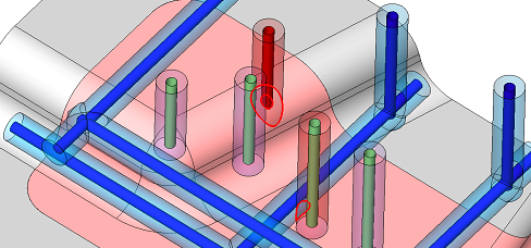
The cooling item hole and its safety offset (Radial Offset and Tip Offset - see above) are displayed as follows:
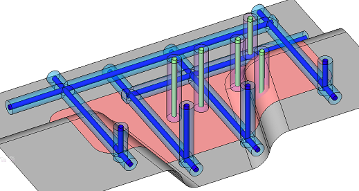
-
The cooling item holes are displayed in green and their safety offsets are displayed in light purple.
-
The cooling faces are displayed in dark blue and their safety offsets are displayed in light blue. The cooling faces are faces belonging to the cooling object, or faces created by the cooling cut (and marked as such).
-
-
Any face (holes and their safety offsets) that has interference with the relevant faces (according to the set parameters) is displayed in red. The interfering area is also displayed in red.
Optional Step 1 
Set the optional offset and rotation parameters. See also positioning parameters.
Optional Step 2 
Select a UCS on the added component to position the component.
Optional Step 3 
The Cut Manager is displayed; select the parts to be cut. This step enables you to manually control which parts are to be cut.
Click OKOK![]() or ApplyApply
or ApplyApply![]() in the Feature Guide to complete the function. In the Assembly Tree, added cooling items are placed in folders under the active sub-assembly.
in the Feature Guide to complete the function. In the Assembly Tree, added cooling items are placed in folders under the active sub-assembly.
When completed, the Add Cool. Item W/Channel feature will appear in the Feature Tree (on the active sub-assembly) as follows:
In addition, a table of baffles is created for all the baffles in the active sub-assembly.
Note: In the Assembly Tree, for files created prior to Cimatron 12.0, added cooling items are displayed as sub-assemblies (instead of placed in folders) under the active sub-assembly.
|