|
|
Manufacturing Attributes : Customized Hole Tolerance: Options and Results
![]()
![]()
The Customized Hole Tolerance attributes allow the attachment of three different attribute types to a hole or a selected group of holes. The available combinations are:
1. Coded
Customized Hole Tolerance attributes in drawings will appear as symbols (images) with the attributes' tolerances shown in Table of Holes (TOH) (with customized holes); Label of Holes (LOH) (with customized holes); and in Dimensions (with customized holes). This data is saved to the actual part file so when sharing your files with other Cimatron users, they will also be able to see these attribute tolerances and symbols.
The steps listed below outline how to:
-
Configure Cimatron to automatically embed marking data in part files and display Customized Hole Tolerance attributes in the Manufacturing Attributes dialog.
-
Add new hole marking symbols by modifying the Marking.elt file.
-
Connect new symbols to Manufacturing Attributes by modifying the HoleMarking.xml file.
-
Apply the Customized Hole Tolerance attributes in the Part and Drafting environments.
-
Attach marking attributes to holes.
Step 1: Setting the Manufacturing Attributes PreferencesStep 1: Setting the Manufacturing Attributes Preferences
Access the Preferences Editor by selecting the Preferences button ![]() from the Quick Access Toolbar or by selecting Tools > Main Tools > Preferences from the menu bar.
from the Quick Access Toolbar or by selecting Tools > Main Tools > Preferences from the menu bar.
PickPick the General preferences item and scroll down to select Manufacturing Attributes.
PickPick Create (Part Environments) and Reload System Definitions . . . options as required. See Manufacturing Attributes preferences for more information.)
Note: The Manufacturing Attributes preferences should be set prior to opening a part or assembly file.
Step 2: Adding a New Marking SymbolStep 2: Adding a New Marking Symbol
The Marking.elt and HoleMarking.xml files are Cimatron system files that contain marking symbols (images) and marking attribute-related data that are required for Cimatron's Customized Hole Tolerance functionality. Cimatron automatically embeds these two files in a part file when the Manufacturing Attributes preferences are set accordingly. The purpose of each file is defined below:
Marking.elt - A Cimatron drafting file that contains marking symbols. This file can customized to create new marking images.
HoleMarking.xml - An XML (Extensible Markup Language) data file that can be customized to display user-defined hole marking attribute data in the Manufacturing Attributes dialog.
These system files are located in the following Cimatron folder:
. . . \ProgramData\Cimatron\Cimatron\2026.0\Data\Hole_Marking
Adding a New Symbol to the Marking.elt file
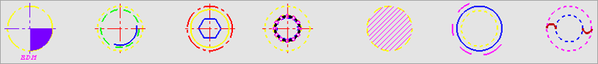
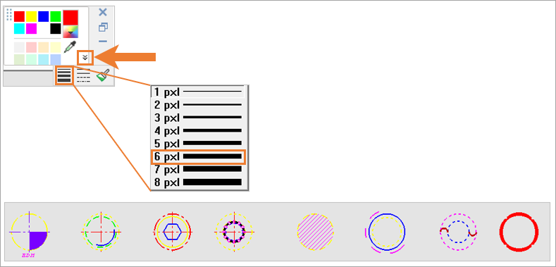
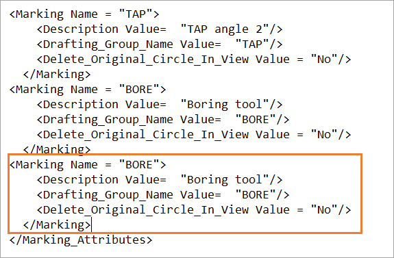
Open the Marking.elt file. The following marking images are displayed:
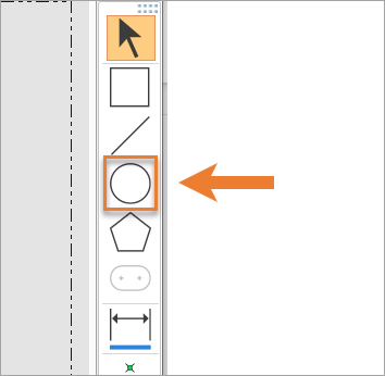
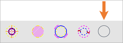
For this exercise, create a new symbol for "Special Bore" by navigating to the Sketcher toolbar and selecting a circle. Draw the circle with a diameter of 20 mm.
 |
 |
Change the circle's color to RED by pickingpicking the circle and selecting the RED color from the Color Picker.
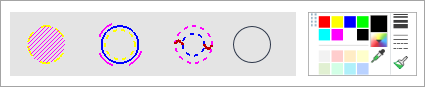
Next, change the circle's line width to 6 pxl by pickingpicking the circle and selecting the 6 px width value.
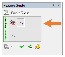
Navigate to Groups in the menu bar and select Create Groups.
PickPick the red circle and exitexit.
PickPick the center point of the circle (this must be center point).
 |
 |
Change the group name by pickingpicking it and typing SP_BORE .
![]()
Save and Close the Marking.elt file.
Step 3: Connecting the New Symbol to Manufacturing AttributesStep 3: Connecting the New Symbol to Manufacturing Attributes
The Marking.elt and HoleMarking.xml files are Cimatron system files that contain marking symbols (images) and marking attribute-related data that are required for Cimatron's Customized Hole Tolerance functionality. Cimatron automatically embeds these two files in a part file when the Manufacturing Attributes preferences are set accordingly. The purpose of each file is defined below:
Marking.elt - A Cimatron drafting file that contains marking symbols. This file can customized to create new marking images.
HoleMarking.xml - An XML (Extensible Markup Language) data file that can be customized to display user-defined hole marking attribute data in the Manufacturing Attributes dialog.
These system files are located in the following Cimatron folder:
. . . \ProgramData\Cimatron\Cimatron\2026.0\Data\Hole_Marking
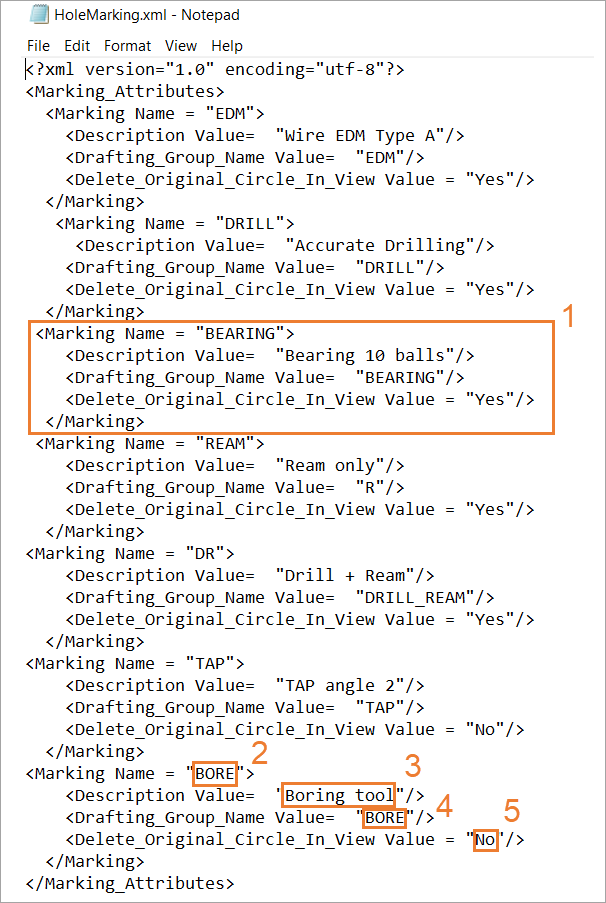
Open the HoleMarking.xml file with a text editing software (Notepad, Notepad++, or WordPad is recommended).
The file's structure is outlined below (as it applies to this exercise).
 |
|
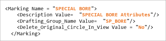
Copy the Bore batch and paste it after the original Bore batch (before </Marking_Attributes>).
Edit the following values in the newly pasted batch:
- Change the Marking Name from BORE to SPECIAL BORE.
- Change the Description Value from Boring tool to SPECIAL BORE Attributes.
- Change the Drafting_Group_Name Value from BORE to SP_BORE.
Note: The Drafting_Group_Name Value must be the same as the name you designated in Step 2, item 8.
- Keep No as the Delete_Original_Circle_In_View Value.
Save and close the HoleMarking.xml file.
Note: You can add multiple attributes to the HoleMarking.xml file. In addition, it is very important that the XML structure not be altered to ensure the data is visible in the Manufacturing Attributes table.
Step 4: Working with Customized Hole Tolerance in the Part EnvironmentStep 4: Working with Customized Hole Tolerance in the Part Environment
As outlined in Step 1, navigate to the Manufacturing Attributes preferences and set the following options:
- Create (Part Environments) option is checked (enabled).
- Reload Systems Definitions . . . option is unchecked (disabled).
Open a part file.
Navigate to the menu bar and pickpick Tools > Main Tools > Manufacturing Attributes.
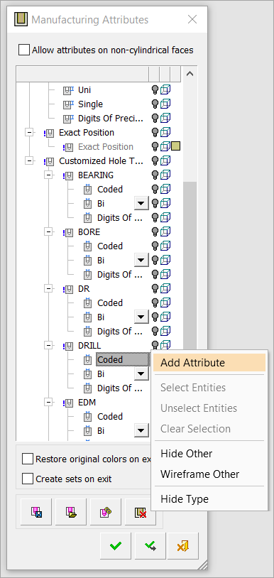
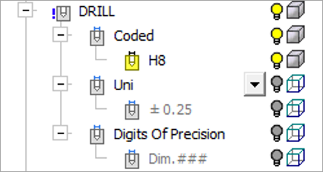
From the Manufacturing Attributes dialog, scroll down to DRILL and clickclick the Coded attribute type.
PickPick Add Attribute.
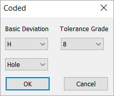
The Coded attribute type dialog appears. Using the Basic Deviation pulldown menu, pickpick H. Then pick 8 from the Tolerance Grade pulldown menu. Pick OK to accept the values.
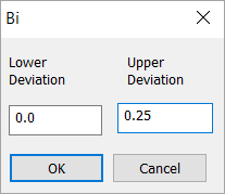
Next, clickclick the Bi attribute type under Drill and select Add Attribute. Navigate to Upper Deviation and change the value to 0.25. Pick OK to accept the change.
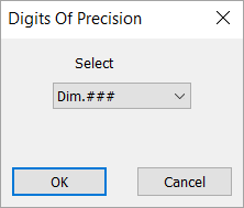
ClickClick the Digits of Precision attribute type under Drill and pickpick Add Attribute. Navigate to the Select pulldown menu and pick Dim.###. Pick OK to accept the change.
Repeat the same process for each of the Customized Hole Tolerance attributes. Note that for some attributes you may need to add two different values. For example:
SPECIAL BORE
Coded: H7; H8
Uni: -0.1, 0.125
Digits of Precision: Dim.##, Dim.###
Step 5: Attaching Marking Attributes to HolesStep 5: Attaching Marking Attributes to Holes
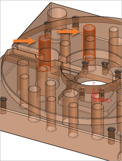
PickPick the inner cylindrical faces of a hole or holes.
In Manufacturing Attributes, scroll down to DRILL and clickclick on H8 (created in Step 4, item 5) under the Coded attribute type and pickpick Attach.
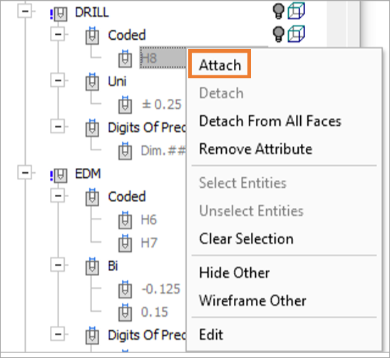
After completing the Attach function, notice that the icon is now highlighted in yellow and that the "H8" text that was previously grayed out is now black.
Repeat the same process for other groups of holes, selecting multiple hole faces and applying the appropriate attributes/values.
Pick the OK button ![]() to accept all changes.
to accept all changes.
Note: You can pick multiple holes at once and attach the same attribute to all picked holes. If you pick the attached attributes, you will be able to see the relevant hole selected on screen.
Step 6: Working with Customized Hole Tolerance in the Drafting EnvironmentStep 6: Working with Customized Hole Tolerance in the Drafting Environment
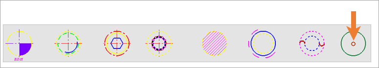
Open a new drafting file.
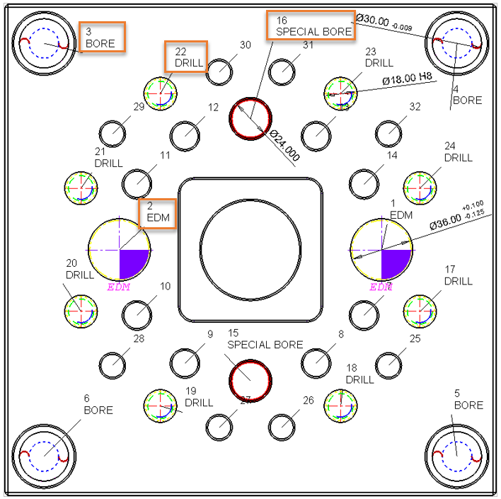
Create a Bottom View for the component.
See the following image as an example for this exercise.
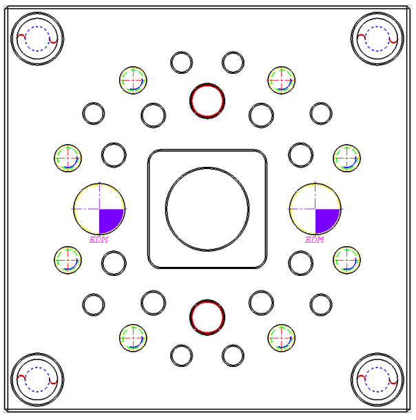
Note: Only holes that are based on a full circle will display a symbol. If a portion of the circle is hidden by an object, the symbol will not be visible.
Invoke Dimension and pickthe symbols to display their properties.
In the image below, note that the EDM symbol has replaced the circle curve. This option was set in Step 3, item 3 by substituting the "No" value with "Yes" for the Delete_Original_Circle_In_View value element. To set a dimension for this circle, select the yellow circle surrounding the symbol.
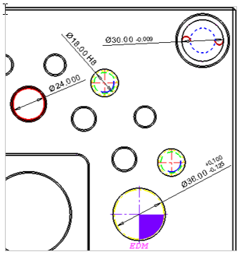
Note: If more than one attribute is attached to a hole, only the first attribute from the group will be displayed in the dimension.
Invoke Table of Holes (TOH) and pick the Bottom View.
Pick OK ![]() to approve Select Origin Point.
to approve Select Origin Point.
Pick anywhere on the graphical area (this picked point will be the corner position of the table).
Pick the Edit Table of Holes icon in the Table of Holes dialog.
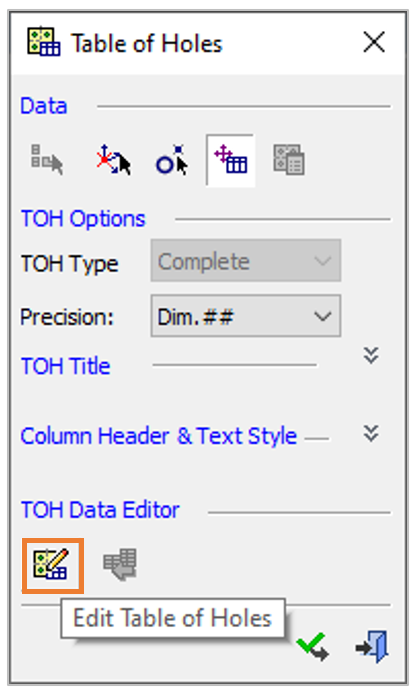
The Table of Holes Editor dialog will appear. Pick the Column Chooser icon.
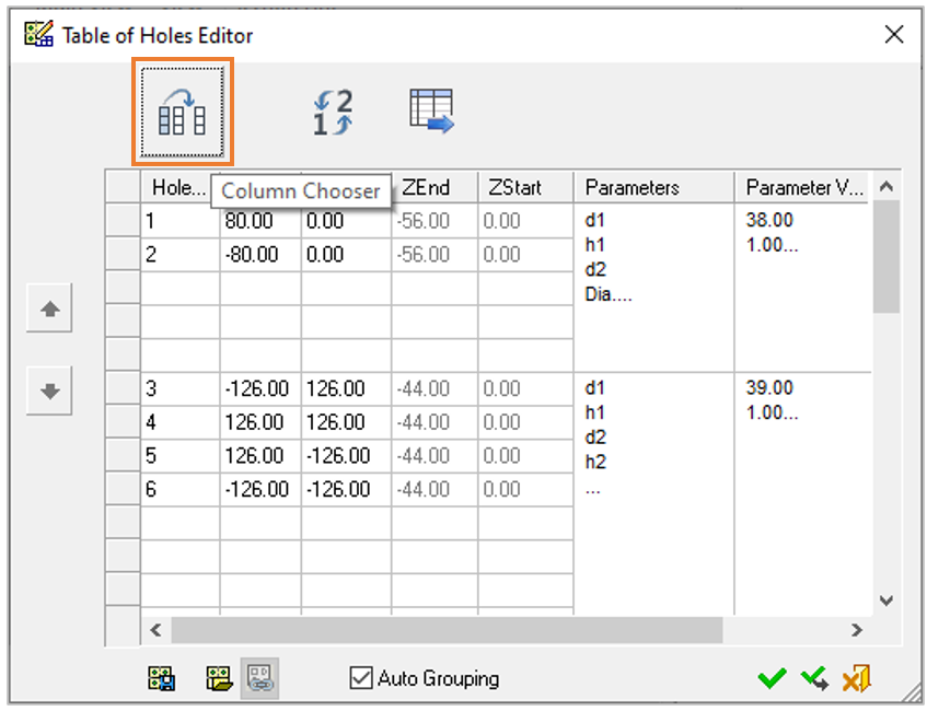
From the Column Chooser dialog, pick Marking Type from the Available Fields column and pick the ADD -> button to add it to the Displayed Fields column. Pick the OK button to accept changes and close the Column Chooser dialog.
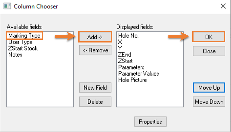
From the Table of Holes Editor, pick the OK button.
From the Table of Holes pane, pick the Close button ![]() .
.
Note that a new column, Marking Type, has been added to the TOH, which displays the Customized Hole Tolerance group name. The attached attributes from the Customized Hole Tolerance group are displayed in the Parameter Values column.
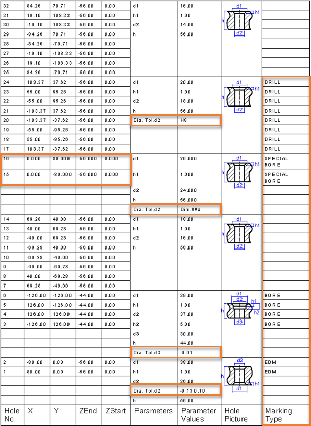
Note: Attaching a Digit of Precision to a hole will affect the XYZ precision of the hole position (see lines 15 and 16 above).
Invoke Label of Holes (LOH) and pick the Bottom View.
Pick the OK button to approve Label of Holes.
Note: The Customized Hole Tolerance group name will be displayed under LOH number.
Save and Close the file.
|