|
|
QuickSplit  : Options and Results

Access: Open this function from one of the following locations:
-
Select Parting > QuickSplit > QuickSplit from the menu bar.
-
Select Parting > QuickSplit from the Mold Design Guide Toolbar or Parting Guide Toolbar.
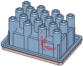
Split faces into opening directions based on their ability to be extruded in those directions and existing parting surfaces.
Split an open or closed object into faces according to specific directions and allow the attaching of special parting attributes to faces/composites. The split information is displayed in the Parting Tree. See the QuickSplit Operation.
During the parting process, QuickSplit and other parting tools can utilize solid body information (from closed and open solids). This does not mean the part has to be a true "watertight" solid body. Even "open" solids contain valuable information that is utilized by Cimatron. This part "topology" provides Cimatron with information about adjacent surfaces, and enables the system to provide various benefits for working with the solid parting process, even those that are problematic and contain faults. Such benefits include:
-
Better, more comprehensive splitting and analysis tools.
-
Increased automation during parting and throughout the tool design process.
Note: After using the QuickSplit function, a parting line can be created along the edges of a split set, which can then be used to create a parting face.
The QuickSplit operation entails the following stages:
Defining the split direction(s) - (creating the split direction sets).
Performing the split operation. At this stage you can also define new split directions and/or create a new parting surface.
If required, use Parting Attributes to assign parting attributes to parting surfaces (faces)parting surfaces (faces).
Parting surfaces are surfaces which are used to separate the core and cavity (and also the slider, if it exists). Parting surfaces do not form the molded part.
If required, use Edit Direction to edit a split direction.
The QuickSplit function can be run from within the Parting and Assembly environments. In the Assembly environment, the modifications are performed directly on the Active Parts and the faces are moved between the parts without regeneration.
Required Step 1 
Assign faces to split direction sets, create new split directions or edit existing split directions.
The following parameters are displayed:
|
|
|
|
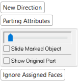
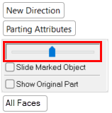
This option enables you to select a new split direction using the directional arrow and returns you to steps 1-4 above. A new split direction can be defined in the Parting environment. A new parting surface direction can be defined in the Parting and Assembly environments. Note: When invoking the QuickSplit function within the Assembly environment, if a parting surface part or a parting sub-assembly (named Parting_<sub-assembly> in the Assembly Tree) is activated, the New Direction option is not displayed. |
|||||||||||||
|
Assign parting attributes to parting surfaces (faces)parting surfaces (faces). This attaches the parting surfaces to opening directions. Parting surfaces separate the core and cavity mold halves; they are the contact surfaces of the two halves of the mold. Parting surfaces do not form the molded part. A feature of the QuickSplit Operation is the ability to show the divided part in motion. In order for parting faces to be included in the motion visualization, they have to be assigned to the two part groups where they shutoff. The Parting Attributes function can perform this assignment automatically. It recognizes which faces are located at the boundaries of different groups of part faces and attaches parting status based on this information. |
|||||||||||||
|
Slide Marked Object |
To split only a specific set of components, select the Slide Marked Object option and click on an object in the Parting Tree. Only this object is split from the original partOnly this object is split from the original part.
|
||||||||||||
|
Show Original Part |
To display the original part during splittingdisplay the original part during splitting, select the Show Original Part option.
|
||||||||||||
|
All Faces / |
Toggle option used to determine which of the relevant faces are to be included in the split direction set, including all faces in the analysis or ignoring previously assigned faces.
|
Set the parameters.
If required, assign faces to different split direction sets. Pick a face (taking into consideration the Ignore Assigned Faces / All Faces toggle option) and attach it to a different split direction.
Note: When attaching a face manually, it is added to the manually assigned faces list. See New Direction > Optional Step 2 for additional information on manually adding faces and how they can be cleared (unselected).
Move the slider ![]() to see how the faces are split.
to see how the faces are split.
|
|
|
Optional Step 1 
Perform the Draft Angle Analysis. Display the Draft Angle Analysis color dialog and show the draft angle when moving the cursor over the faces selected for assignment.
Press Close ![]() in the Feature Guide to complete the function.
in the Feature Guide to complete the function.
Notes:
-
Under the Assembly environment, the QuickSplit behavior is the same as under the Parting environment.
-
The QuickSplit analysis will never run inside activated parts in the MoldDesign environment. This means that the function will not open at the New Direction feature guide.
-
Faces can be selected only from Active Parts.
-
The attached faces will get the attribute of the target direction.
-
If required, the split 'state' can be Published to PDF.
|