|
|
Blank (Electrode)  : Options and Results


Access: Activate the appropriate Electrode
![]() or a Location
or a Location ![]() in the Electrode Tree, and then invoke this
function from one of the following locations:
in the Electrode Tree, and then invoke this
function from one of the following locations:
-
Select Electrode > Geometry > Blank from the menu bar.
-
Select Blank from the Electrode Guide.
Create or edit the blank for the electrode, using finite element analysis (FEA).
Notes:
-
Only one Blank feature per electrode can be created. If the Blank function is invoked after a Blank has been created, the function will be invoked in edit mode.
-
This function is only available when an electrode is active in an assembly environment.
Required Step 1 
Set the appropriate parameters:
|
|
|
Toggle the parameters expand/collapse button  /
/ to display sizing and positioning parameters relevant to the shape of the Blank and Base.
|
Blank shape parameters (see Blank Parameters below): |
Base shape parameters (see Base Parameters below): |
||
|
|
|
|
|
| Blank parameters: The 'shape' parameters that are displayed depend on the shape of the blank: | |||||||||||||||
|
Rectangular |
This is a toggle parameter enabling you to define the shape of the blank: Rectangular / Cylindrical.
|
||||||||||||||
|
Blank Wire Frame |
This is a toggle option Blank Wire Frame / No Blank enabling you to display the blank with or without a wireframe body.
Notes:
|
||||||||||||||
|
Free Blank Size |
This is a toggle parameter enabling you to define how to set the size of the blank: Free Blank Size / Use Blank Library.
|
||||||||||||||
|
X/Y/Z Position |
Toggle the parameters expand/collapse button The size and position of the blank can be set either dynamically, by entering numeric values (see below) or by setting a direction. Numeric values examples:Numeric values examples:
To define the rotation angle of a cylindrical or rectangular blank, either set the Angle value (entering numeric values manually) or by selecting a Direction (using the direction arrow) to define any direction as the +X direction of the blank. See the example. Adjust the parameter values as required. The default sizes of the blanks are set in the Electrode Preferences. |
||||||||||||||
|
Angle |
|||||||||||||||
|
Direction |
|||||||||||||||
|
|
|||||||||||||||
| Base parameters: The 'base' parameters that are displayed depend on the shape of the base and also the shape of the blank (see above): | |||||||||||||||
|
Base |
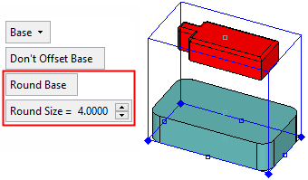
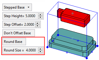
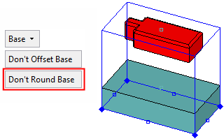
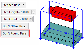
From the dropdown list, select the type of Base for the Blank. The Base is the part of the blank that is not milled. The following Base types are available:
The following parameters are displayed according to the selected base type and also the blank shape:
|
||||||||||||||
|
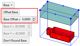
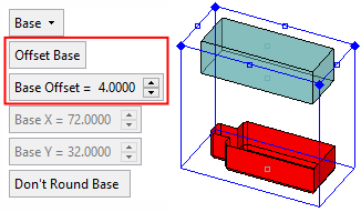
Offset Base |
This is a toggle parameter that enables you offset or to not offset the base from the blank. The toggle options are Offset Base / Don’t Offset Base. When offsetting the base, this creates a base that is slightly smaller than the blank. This enables the base to be machined completely and not just up to its top face.
Notes:
|
||||||||||||||
|
Round Base |
This is a toggle option Round Base / Don't Round Base that enables you to automatically round sharp corners in the electrode base. This option is only displayed if a Rectangular blank is selected above. The rounding defaults are set in the Electrode Preferences.
Notes:
|
||||||||||||||
|
Blank Height |
Select and set the parameters used in the blank definition. Three of the displayed parameters are always available for defining the blank; these parameters are displayed with orange buttons. One of the parameters is always grayed out (unavailable). When pressing one of the three orange (available) buttons, the selected button becomes grayed out (unavailable) and the previous grayed out button becomes orange (available). The blank is always defined by three of the following parameters:
|
||||||||||||||
Optional Step 1 
Center to selection. Center the blank over the burn face. The size of the blank remains the same.
Note: The electrode blank can also be Re-Centered, at a later time, to all the electrode faces (burn faces, extension and manually created faces).
|
Before:
|
After:
|
Optional Step 2 
Fit to selection. Fit the blank over the burn face with a predefined offset. The size of the offset around the attached face is defined in the Electrode Preferences.
Note: The electrode blank can also be Re-Fit, at a later time, to all the electrode faces (burn faces, extension and manually created faces).
|
Before:
|
After:
|
Optional Step 3 
Mark the base of the blank or only the step. The base is often marked by a chamfer or a round on one of its edges. The mark helps the machine operator to position the electrode correctly on the EDM machine.
The mark options depend on the shape of the blank.
Rectangular Blanks
![]()
An Electrode Preference option sets the default rules for the rectangular marking.
|
Chamfer |
From the dropdown list, select the type of mark Round, Chamfer or None. For Round or Chamfer, define the size of the mark. The round or chamfer can be created on the step only (see below) and not the entire blank.
The mark can be applied to the corner of the base which is closest to the reference UCS, or it can be applied to a predefined corner. |
||||||
|
Size |
Set the size of the mark. The examples below are for a Chamfer mark.
|
||||||
|
Entire Blank |
This is a toggle option Entire Blank / Step Only.
|
Circular Blanks
![]()
An Electrode Preference option sets the default rules for the circular marking.
|
Mark Base |
From the dropdown list, select Mark Base or None. For Mark Base define the size of the mark.
|
||||
|
Height |
The height of the mark.
|
||||
|
Depth |
The distance from the exterior wall of the base to the wall of the mark.
|
||||
|
Angle |
Angle of the plane of the mark from the active UCS (the default is 0). |
Press <exit><exit> when finished. Click OKOK![]() or ApplyApply
or ApplyApply![]() in the Feature Guide to complete the function.
in the Feature Guide to complete the function.
When completed, the Blank feature will appear in the Feature Tree as follows:
![]()

|