|
|
Mold Design Menu: Cooling Design Tools

Access: Open this group of functions from one of the following locations:
-
Select Mold Design > Cooling from the menu bar. Select the required function.
-
Select Cooling from the Mold Design Guide Toolbar. Select the required function.
This group of functions is used to quickly and easily design cooling channels in the mold using a specialized group of functions that simplify the creation of complex cooling systems.
|
|
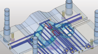
An example of a ooling system is shown below:
|
The cooling design process begins with a user sketch of the channels and ends with the addition of cooling items to the channels. Cooling Part and Cooling Channel features are created. See the Cooling Tips. Important: The cooling channel is created only in components that are assigned to the active assembly. The Cimatron Cooling Design functions enable you to:
This provides you with:
|
|
|
In the example above, the system has located a collision with an ejector, and displays a red intersection curve in the area where the collision occurs. |
|
|
|
|
|
Cooling tip types. |
The following functions are available in this group:
|
|
||
|
|
Add cooling items (plugs, nipples, baffles, and so on) from the catalog and create cooling channels for them. |
|
|
|
Analyze and mark faces belonging to conformal cooling circuitscooling circuits and cooling items. Conformal cooling circuits are those that are conformal to the shape of the product. |
|
|
|
Analyze and mark faces belonging to cooling circuitscooling circuits and cooling items. |
|
|
|
Automatically create conformal cooling curves by analyzing the part's geometry. |
|
|
|
Create complex conformal cooling channels. |
|
|
|
Cut the mold plates and inserts by cooling objects (cooling channels) and cooling items (nipples, plugs, etc.). |
|
|
|
Analyze and create a color map of distances between cooling channels and cooled part faces. |
|
|
|
Create text labels next to cooling holes. |
|
|
|
Create a line to be used as a cooling line in a cooling part. A cooling part will be created if it does not already exist. |
|
|
|
Create an object that will define the holes that will be created around the cooling lines. |
|
|
|
Create a sketch of cooling lines in a cooling part. A cooling part will be created if it does not already exist. |
|
|
|
Verify safety distances between all hole types (cooling holes and non-cooling holes) and the distances between holes and part faces to ensure that these distances are above a defined safety threshold. |
|
|
|
Create an inclined plane (in a cooling part) to have cooling lines created on it. A cooling part will be created if it does not already exist. |
|
|
|
Create a parallel plane (in a cooling part) to have cooling lines created on it. A cooling part will be created if it does not already exist. |
|
|
|
Remove the holes of connected cooling lines. This enables you to quickly edit cooling systems. |
|
|
|
Create a Table of Baffles. The function automatically selects known baffles, numbers them, and creates corresponding numbers as engravable text on the baffles and their holes in the plate. Several options allow you to control the numbering scheme as well as the size and style of the text. In addition, the function also outputs a full table of the baffles to an Excel report, with information such as the baffle diameter, length, XY location, and BOM ID number. |
Cooling Part
When entering any of the Cooling functions for the first time, per assembly, MoldDesign automatically creates a Cooling Part in the activated assembly. This cooling part contains all the cooling features, such as datums, sketches and cooling channels.
The cooling part behaves as a standard Cimatron part that was created in the assembly environment. Note that MoldDesign creates only one cooling part per assembly. The Cooling Part can contain many cooling objects.
Cooling Channel
When creating the cooling channel, MoldDesign automatically analyzes which components will be cut and uses the cooling part as the cutting object. Note that this cutting operation takes place in the assembly environment and is based on the Assembly Cut operation.
Within every part that is cut by the Cooling Part, a standard Cut feature is created.
Cooling Tips
-
Using an existing cooling sketch as a reference (useful for the creation of similar channels in parallel planes): Activate the cooling part, pick the cooling sketch and select Show Sketch in the popup submenu (right mouse click).
-
3D cooling channels: You can create regular a 3D composite curve in the required cooling part, then activate the Cooling Channel (to create the channels) in the relevant assembly and select the composite curve as the cooling sketch.
-
Instance: Design the cooling in one instance only. The channel will be created in all instances. If you want to design a different cooling channel for each instance, use the "Save As" option before adding them to the assembly.
|