|
|
Relocate Component  : Options and Results
Access: Open this function from one of the following locations:
-
Click the
 button in the toolbar.
 -
Select Assembly > Quick Modification Tools > Relocate from the menu bar.
-
Select Relocate on the Graphics Area popup menu.
Move components around with or without updating their Add operation parameters.
This function is used to relocate components in an assembly (irrespective of the types of connection) with or without regenerating other parts. The function should be used instead of Edit Add in very large assemblies, when regeneration is very slow or not possible. See the results of a relocation, in connection terms.
Note: Before using this function, it is recommended that you use Remove Pocket to remove the cut faces of components to be relocated, otherwise the current pockets will continue to be displayed after the components are relocated (as regeneration does not take place).
Required Step 1 
From the active assembly, pick the components to be relocated. Selecting a part from a sub-assembly, will select the whole sub-assembly.
|
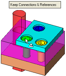
Pick the component(s) (from the active assembly) to be relocated. Select by Box can also be used for picking the components. |
The component object is selected. |
|
|
|
Set the locating options. The following toggle options are displayed:
|
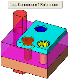
Keep Connections & References |
Relocate the selected components while keeping original ties and connections to surrounding components. This is the default option. With this mode, after components have been relocated, they are kept associative to the original add operation and behave as the same as "individually controlled" components. This mode can be used to edit the location of components that were added using the Place on Face, Place on Cone Face, Place by UCS and On Assembly UCS type operations. |
|
Break Connections & References |
Relocate the selected components while breaking original ties and connections to surrounding components. When this option is selected, an appropriate warning message is displayed informing you that the connections and references will be broken. |
Press <exit><exit>.
Required Step 2 
Set the locating options. The following options are displayed:
|
|
|
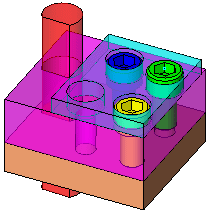
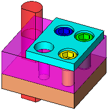
In the pictures below, note that after the component is relocated, the original cut faces (pockets) are still displayed. This is because the original cut faces were not removed prior to running this function. See the 1st Note above.
For all these options, set the With Cut / Without Cut toggle option, if it is displayed (this option is unavailable if the Keep Connections & References option was selected in the 1st step).
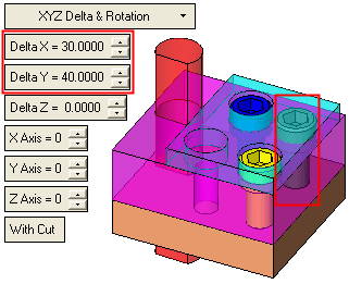
XYZ Delta & Rotation
Set the offset and rotation parameters. Either click on the field and enter the new value, or use the arrows to increase or decrease the value.
Note: The delta offset parameters (in this step) are based on the main assembly UCS. If this UCS is not appropriate for the relocating operation, pick another UCS to define the delta offset direction, using the 2nd optional step of this function. The rotation parameters are always based on the active UCS of the relocated part.
|
Set the appropriate parameters. |
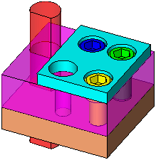
The component in the new location. |
|
|
|
In the above pictures, notice that after the component is relocated, the original cut faces (pockets) are still displayed. This is because the original cut faces were not removed prior to running this function. See the 1st Note above.
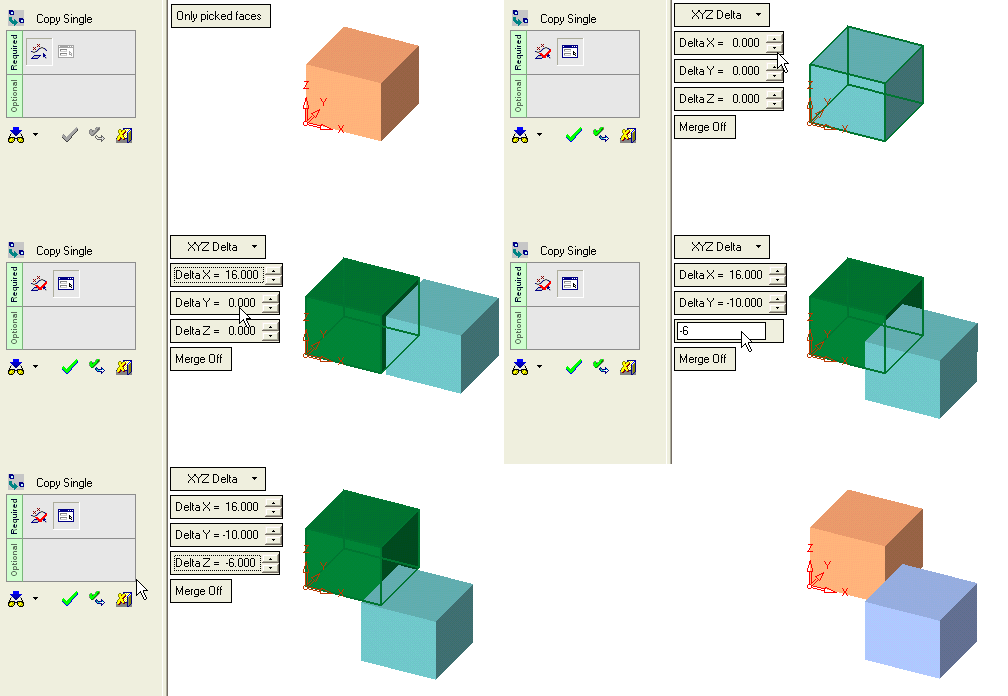
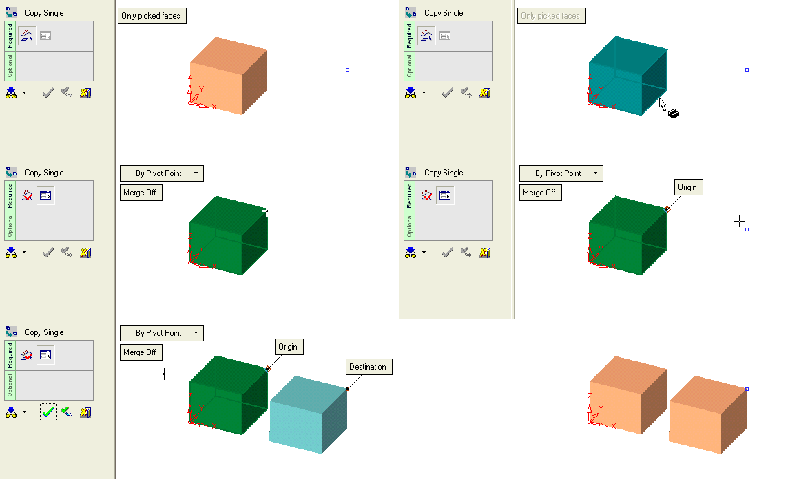
The Delta Offset behavior is similar to that of the Copy function in the Part environment:
|
Demo: Press the button below to view
a short movie demonstrating the function:
|
Practice: Press the button below to open Cimatron with a practice ELT file similar to that used to create the movie (if the relevant feature already exists in the ELT file, you can either edit it or delete it and create a new feature). |
|
|
|
From Point to Points
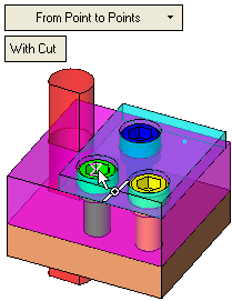
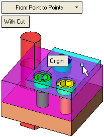
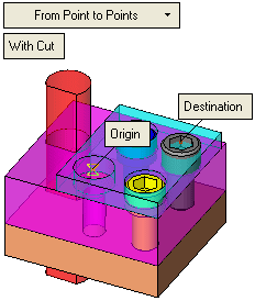
Select first the origin point and then the destination point that determines the relative copying vector. (See Picking Points.) If you want to change the destination, click the existing destination point and then choose a new point. To reselect both points, click the existing origin point and then reselect both points.
|
Select the origin point. |
Select the destination point. |
|
|
|
|
The component in the new location. |
|
|
|
|
In the above pictures, notice that after the component is relocated, the original cut faces (pockets) are still displayed. This is because the original cut faces were not removed prior to running this function. See the 1st Note above.
The From Point to Points behavior is similar to that of the Copy function in the Part environment:
|
Demo: Press the button below to view
a short movie demonstrating the function:
|
Practice: Press the button below to open Cimatron with a practice ELT file similar to that used to create the movie (if the relevant feature already exists in the ELT file, you can either edit it or delete it and create a new feature). |
|
|
|
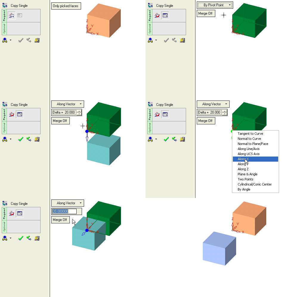
Along Vector
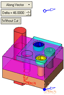
Use the blue arrow to set the vector direction, and set the delta value - the absolute distance by which the entities will move. You can click on the arrow head or body to reverse the direction.
|
Set the required vector direction and delta distance. |
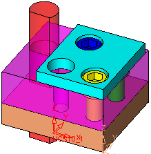
The component in the new location. Note that the Without Cut option was selected. |
|
|
|
In the above pictures, notice that after the component is relocated, the original cut faces (pockets) are still displayed. This is because the original cut faces were not removed prior to running this function. See the 1st Note above.
The Along Vector behavior is similar to that of the Copy function in the Part environment:
|
Demo: Press the button below to view
a short movie demonstrating the function:
|
Practice: Press the button below to open Cimatron with a practice ELT file similar to that used to create the movie (if the relevant feature already exists in the ELT file, you can either edit it or delete it and create a new feature). |
|
|
|
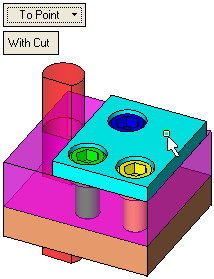
To Point
Pick the point to where the component(s) is to be relocated.
|
Pick the point. |
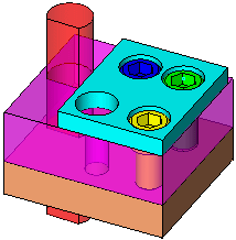
The component in the new location. |
|
|
|
In the above pictures, notice that after the component is relocated, the original cut faces (pockets) are still displayed. This is because the original cut faces were not removed prior to running this function. See the 1st Note above.
Note: If the relocated component has a UCS to Face connection, the target point can only be selected from the part that owns that same face.
Press <exit><exit> when finished. Press OK ![]() or Apply
or Apply ![]() in the Feature Guide to complete the function.
in the Feature Guide to complete the function.
Optional Step 1 
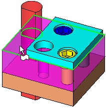
Pick a face so that the relocated component has a UCS to Face connection with the selected face.
|
Pick a face. |
The component in the new location. |
|
|
|
In the above pictures, notice that after the component is relocated, the original cut faces (pockets) are still displayed. This is because the original cut faces were not removed prior to running this function. See the 1st Note above.
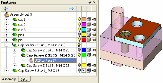
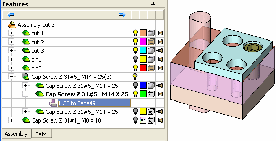
The Assembly Tree confirms that the relocated component has a UCS to Face connection with the selected face. The previous connection was a UCS to Face to the top faceUCS to Face to the top face.
Optional Step 2 
Pick a UCS to define the delta offset direction; any UCS can be selected. This optional step is only available if the XYZ Delta & Rotation option is selected in the 2nd required step. The delta offset parameters (in the 2nd required step) are based on the main assembly UCS. If this UCS is not appropriate for the relocating operation, pick another reference UCS to define the delta offset direction.
Note: This optional step only affects the delta offset parameters, as the rotation parameters are always based on the active UCS of the relocated part.
When this optional step is activated, all hidden UCSs in all relocated components are shown. Pick one of these UCS's or any other UCS in the assembly.
After the selection:
-
The Feature Guide will automatically switch to the 2nd required step
-
The preview will show the updated location of the component being relocated (based on the selected UCS).
-
The button for this step will be marked with a red check mark.
Pressing <exit><exit> in this step without selecting a UCS will also switch the Feature Guide to the 2nd required step.
Optional Step 3  :
:
The Cut Manager is displayed; select the parts to be cut. This step is used to manually control which parts are to be cut.
Results of a Relocation
The results of a relocation in connection terms, are as follows:
If there was no connection, a new connection is not created. An exception to this is if the 1st optional step is used, in which case a UCS to Face connection is created.
If there was any connection (except a UCS to Face), a new UCS to UCS (UCS of the active assembly) connection is created.
If there was a UCS to Face connection, this connection remains.
|

