|
|
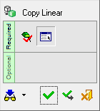
Copy Linear 


Access: Open this function from the following location:
-
Select Edit > Move & Copy > Copy Linear from the Part menu bar.
Copy geometry along a direction. Multiple copies in various directions can be created.
There are several options for setting the location or direction of the copied entities.
The following is the Feature Guide for Copy Linear.
|
|
|
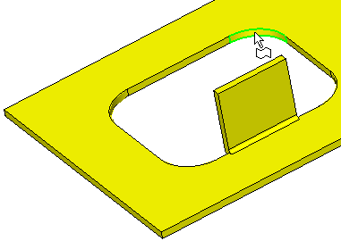
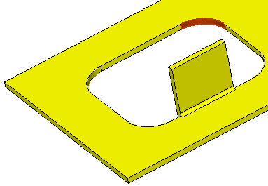
Required Step 1 
Pick the entities to be copied. All types of entities can be picked. The cursor will indicate what you are picking, and you can use various geometry selection tools such as the Selection Filter or the Face Selection Options to enable you to pick the entities you want.
If the Faces filter is selected, the following interaction is displayed:
|
|
|

If the Faces filter is selected (see Selection Filter or Quick Filter), the Include the entire feature / Only picked faces toggle option is displayed:
|
Include the entire feature |
All faces belonging to the same feature (created by the same function) will be automatically selected.
|
|
Only picked faces |
Only individually picked faces are selected.
|

This toggle option will not appear if you select objects, curves, sketches, or faces of different features.
Press <exit><exit> when the required entities are picked.
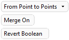
Required Step 2 
Select the type of linear copy operation. The following options are available:
 |
 |
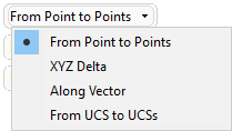 |
The following options are available:
When copying several faces from the same body, the faces are not unstitched, but keep the original topology. This does not apply if the Merge On option is used (when available).
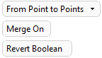
The Merge On field means that all copied items will be part of the same object as the original. Toggle to Merge Off if you want each copied item to be an individual object. See the Merge On/Off example below.
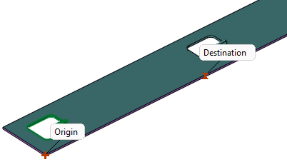
- Copy the selected geometry from an origin point to one or more destination points.
- Select the origin point and then select one or more destination points that determine the relative copying vector. (See Picking Points.)
- To change the destination, click an existing destination point and then choose a new point.
- To reselect both points, click the existing origin point and then reselect both points.
See Single and Multiple Destinations below.
From Point to Points > Single Destination
 |
 |
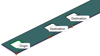
From Point to Points > Multiple Destinations
Multiple destination points can be picked by using "box selection".
|
 |
A Triad symbol is displayed.
- Copy the selected geometry along a delta XYZ of the Triad and/or rotate around one or more selected axes of the Triad.
- Either set the values in the parameter fields or use the displayed Triad to drag and/or rotate the geometry.
When dragging geometry along an axis, or rotating around an axis on screen, the Triad symbol is displayed.
Example:Example:
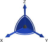
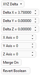
The Triad allows dragging in 3D, along the X, Y, and Z axes or on the XY, XZ and YZ planes (as well as free dragging). It also allows rotation dragging around each one of the axes (X axis, Y axis, or Z axis). The Triad Data Pane is displayed when dragging or rotating objects, providing real-time delta movement information.
 |
 |
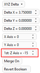
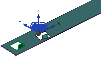
Use this option to rotate the selected entities around one or axes of the Triad. Either use the Triad for dragging and rotating, or set values in the parameter fields.
In the example below, a parameter field is used to define the rotation angle around the Z axis of the Triad.
 |
 |
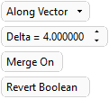
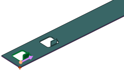
Use the blue arrow to set the vector direction, and set the delta value - the absolute distance by which the entities will move. You can click on the arrow head or body to reverse the direction.
 |
 |
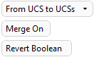
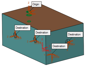
Select the origin UCS and then select one or more destination UCSs. To change the destination, click an existing destination UCS and then choose a new UCS. To reselect both UCSs, click the existing origin UCS and then reselect both UCSs.
 |
 |
Merge On: This is a toggle option Merge On / Merge Off enabling you to select whether to merge the selected faces with the body to which the faces belong (using a cut and merge boolean operation), or to keep the selected faces as individual faces and do not cut and merge.
When moving several faces from the same body, the faces are not unstitched but keep the original topology.
|
Merge On |
Merge the selected faces with the body to which the faces belong (using a cut and merge boolean operation).
|
|||
|
Merge Off |
Keep the selected faces as individual faces and do not cut and merge.
|
|||
|
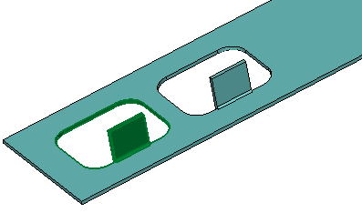
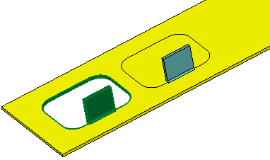
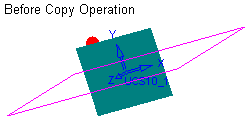
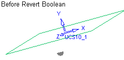
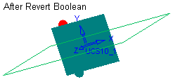
Revert Boolean |
When using the Merge On mode, in some cases an undesirable result is obtained. The Revert Boolean button allows the correct Boolean operation to be performed. The bounded face copied below causes the main geometry to disappear. Pressing the Revert Boolean button corrects this result.
This option is displayed if the following combinations of options are used:
|
Note: An additional screen parameter, the toggle option Don't Change Colors / Overwrite Colors, is displayed when editing the following Copy features: Copy Linear, Copy Linear Array, Copy Radial Array and Copy Mirror. See Editing Copy Features.
When you are finished, press OK ![]() or Apply
or Apply ![]() in the Feature Guide to complete the function.
in the Feature Guide to complete the function.
When completed, the Copy Linear feature will appear in the Feature Tree as follows:

|