|
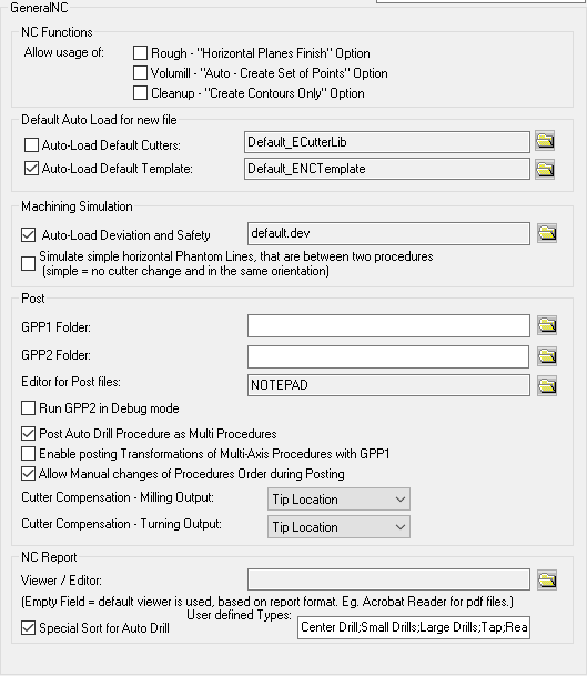
NC Functions
|
Set defaults for enabling the usage of the following:
Note: The options in this section are only enabled when all NC procedures are closed.
|
|
Rough - "Horizontal Planes Finish" Option
|
When this checkbox is marked  , the option Horizontal Planes Finish is displayed in the Vertical Step Type parameter for the Rough Parallel and in Rough Spiral procedures. , the option Horizontal Planes Finish is displayed in the Vertical Step Type parameter for the Rough Parallel and in Rough Spiral procedures.
The Horizontal Planes Finish option finds and machines all horizontal planes among the selected surfaces.
Default = OFF 
|
|
Cleanup - "Create Contours Only" Option
|
When this checkbox is marked , the procedure Cleanup - Contours Only is displayed in the Remachine subselection dropdown list.
To enable the use of any cutter combinations, the Cleanup - Contours Only procedure enables the creation of auxiliary contours in the Cleanup procedure, without creating motions. These contours can then be used later as input to any other procedure.
Default = OFF
|
|
Volumill "Auto Create Set of Points" Option
|
When this checkbox is marked , the option Auto - Create Set of Pre-Drill Points is displayed in the Entry Points dropdown list of options in the Entry and End Points parameter table for newly created VoluMill Pocket and VoluMill Rough procedures.
Default = OFF
|
|
Default Auto Load for new file
|
Set defaults when loading a new file.
|
|
Auto-Load Default Cutters
|
The following parameters can be set in this section:
-
Auto-load Default Cutters for new file: When this checkbox is marked , define whether to automatically load the default cutters (Cutter Library) for each new NC file.
Default = OFF
-
The file of the Default Cutters: The location of the Cutter Library is displayed.
This should either be the default cutter library or the full path name of an .elt file that holds your specific Cutter Library.
Default Cutter LibraryDefault Cutter Library
The default Cutter Library is defined as Default_ECutterLib.
This points to folder ...\Data\IT\var\profiles\ of your installation, which holds the following cutter library files:
Tool_INCH_Lib.chl
Tool_MM_Lib.chl
If required, press the Restore Default button  from the approval options to restore the default Cutter Library. from the approval options to restore the default Cutter Library.
Loading the Cutter Library loadedLoading the Cutter Library loaded
When you create a new NC file, you need to define its units of measurement. When selecting a cutter from the Cutter Library, the appropriate INCH or MM library .elt file is loaded. For example, if you selected MM as the units of measurement, the cutter library is loaded from file Tool_MM_Lib.elt.
|
|
Auto-Load Default Template
|
The following parameters can be set in this section:
-
Auto-load Default Template for new file: When this checkbox is marked , define whether to automatically load the default NC Template for each new NC file. This option can be used to automatically create NC Setup, Stock and Part as well as any other TP Folder(s) and Procedure(s). The NC Template can be a single TP (toolpath) template (.tpt) or a multi TP template (.mtt).
Default = ON  . .
-
The file of the Default Template: The location of the default template is displayed.
This should either be the default template or the full path name of the file that holds your specific template.
Default templateDefault template
The default template is defined as Default_ENCTemplate. This points to folder ...\Data\IT\var\profiles\ of your installation, which holds the default template file Default_ENCTemplate.tpt.
If required, press the Restore Default button from the approval options to restore the default template.
|
|
Machining Simulation
|
Set defaults for the Simulator.
|
|
Auto-Load Deviation and Safety
|
When this checkbox is marked , save the deviation table values and colors, as well as the safety offset values of the simulator.
Default = ON .
The machining simulation deviation table values and colors are saved in a template file with the suffix DEV and stored in the following default folder:
...\ProgramData\Cimatron\Cimatron\2026.0\Data\Nc\Deviation
|
|
Simulate Simple horizontal phantom lines
|
When this checkbox is marked , simulate horizontal phantom lines between two procedures during simulation, where there is no cutter change and where the cutters are in the same orientation.
|
|
Post
|
The following parameters can be set in this section:
-
GPP1/GPP2 Folder: Set default folders for GPP and GPP2 program files. This enables you to specify any folder or network location to store your post processor files. If these fields are empty, the program files that are used are those in the following folders of your installation:
For GPP:
...\ProgramData\Cimatron\Cimatron\2026.0\Data\It\var\post
For GPP2:
...\ProgramData\Cimatron\Cimatron\2026.0\Data\It\var\post2
-
Editor for Post files: Define the default editor for Post Processor files. Microsoft (R) Notepad is the default system editor, however, you can define any text editor.
This field is for GPP only.
For GPP2, you need to edit the ...\Program\GcodeEditor.bat file and define the program and path of the editor that you want to use.
-
Run GPP2 in Debug mode: Define the GPP2 operating mode:
|

OFF
|
The GPP2 runs in the background directly from Cimatron with no live interaction. This operating mode is for G-Code creation.
This is the default option.
When operating in 'background mode', a line representing the GPP2 processing job is displayed in the NC Execution Monitor. You can monitor (using the progress bar) and terminate the GPP2 post, by using the NC Execution Monitor. When changes in the NC file cause the GPP2 processing job to become irrelevant, an appropriate message is displayed and you can terminate the job.
|
|
ON
|
The GPP2 runs as a standalone application. When the OK or Apply buttons are clicked in the Post Process dialog, the GPP2 Runtime Environment dialog displayed. This operating mode is mainly for Post Processor developers.
|
-
Post Auto Drill Procedure as Multi Procedures: When this checkbox is marked , an Automated Drill procedure with multiple data sets (cutters/parameters) is split into many procedures - each with a unique data set. Select this option if you are using an old Post Processor which does not support multiple cutters in a single procedure.
-
Enable posting Transformations of Multi-Axis Procedures with GPP: When this checkbox is marked , Transformations of procedures with multiple axes, can be posted using the GPP. For the Cimatron GPP2 General Post Processor, this checkbox is irrelevant as GPP2 supports Transformations of procedures with multiple axes.
-
Allow Manual changes of Procedure Order during Posting: When this checkbox is marked , this enables you to manually rearrange the order of the selected procedures for the required process.
Default = ON .
-
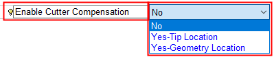
Cutter Compensation - Milling Output: Select a default cutter compensation mode. The following options can be defined, Tip Location and Geometry Location See Cutter Compensation for details.
Default = Tip Location.
In the relevant NC procedure, the cutter compensation mode is displayed in the Enable Cutter Compensation field of the procedure's parameter table grid, under Machine Parameters.
-
Cutter Compensation - Turning Output: Select a default cutter compensation mode. The following options can be defined, Tip Location and Geometry Location See Cutter Compensation for details.
Default = Tip Location.
In the Turning > Contour procedure, when exiting the Process dialog with the Cutter Radius Compensation On checkbox set to ON  , the default Preference compensation option is displayed, dimmed, in the Enable Cutter Compensation field of the procedure's parameter table grid under Machine Parameters; for example: , the default Preference compensation option is displayed, dimmed, in the Enable Cutter Compensation field of the procedure's parameter table grid under Machine Parameters; for example:

|
|
NC Report
|
The following parameters can be set in this section:
-
Viewer / Editor: Define the default application (software) that is used to view the selected output format of the NC Report. For example, the MHT format can be viewed with Microsoft Internet Explorer or Microsoft Office.
This is only relevant if the Standard report type is selected within the NC Setup Report dialog.
This field is empty by default, which means that the default viewer is being used (based on the output format of the report).
Note: A number of output formats are available and, depending on the chosen file format, the generated report will be opened in the appropriate viewer. See the NC Standard Report for the list of currently supported output formats.
|
|
Special Sort for AutoDrill
|
This parameter is used to define cutter types (cutter families) to enable the automatic sorting of cutters inside an Automated Drill procedure. The cutter sorting rules are based on the recognition of the cutter type.
When this checkbox is marked , an additional parameter, User-Defined Types, is available. This field is used to enter the various user-defined cutter type names, separated by a semicolon.
Default = OFF
Automated Drill User-Defined Cutter Sorting
The process to enable the automatic sorting of cutters inside an NC Automated Drill procedure, is as follows:
Define the cutter types (cutter families). In the General NC preferences, set the Special Sort for AutoDrill checkbox to ON and define the various cutter types.
Define the sort order of the cutter types. In Special Automated Drill Sort preferences, set the Use Special Sort checkbox to ON, add the cutter type (defined in #1) and define the sort order within the cutter type.
For each cutter in the cutter table, define to which cutter type it belongs. In the Motion Param. tab and the Cycle Param. tab of the Cutters & Holders dialog, select the cutter type from the Automated Drill Sort Cutter Type dropdown list. This dropdown list is only displayed if the Use Special Sort checkbox (#2) is set to ON.
In the Automated Drill procedure Drill Parameters table, set the Process Optimization parameter to the By Cutters by User Order option. This option is only available if the Use Special Sort checkbox (#2) is set to ON
In the Automatic Drill Cutter List dialog, the value in the column Cutter Type column is as defined for each cutter in the Cutters & Holders dialog (#3). The Cutter Type column is only displayed if the Process Optimization parameter is set to the By Cutters by User Order option (#4).
Note: Cutters used by the Automated Drill procedure that have not been defined a cutter type (#3), or have a value that does not appear in the Special Sort for AutoDrill list (#1), will assume the lowest priority in the sort order.
|

 from the Quick Access Toolbar, or