Process Manager: Table 
![]()
![]()
Access: Open this function from one of the following locations:
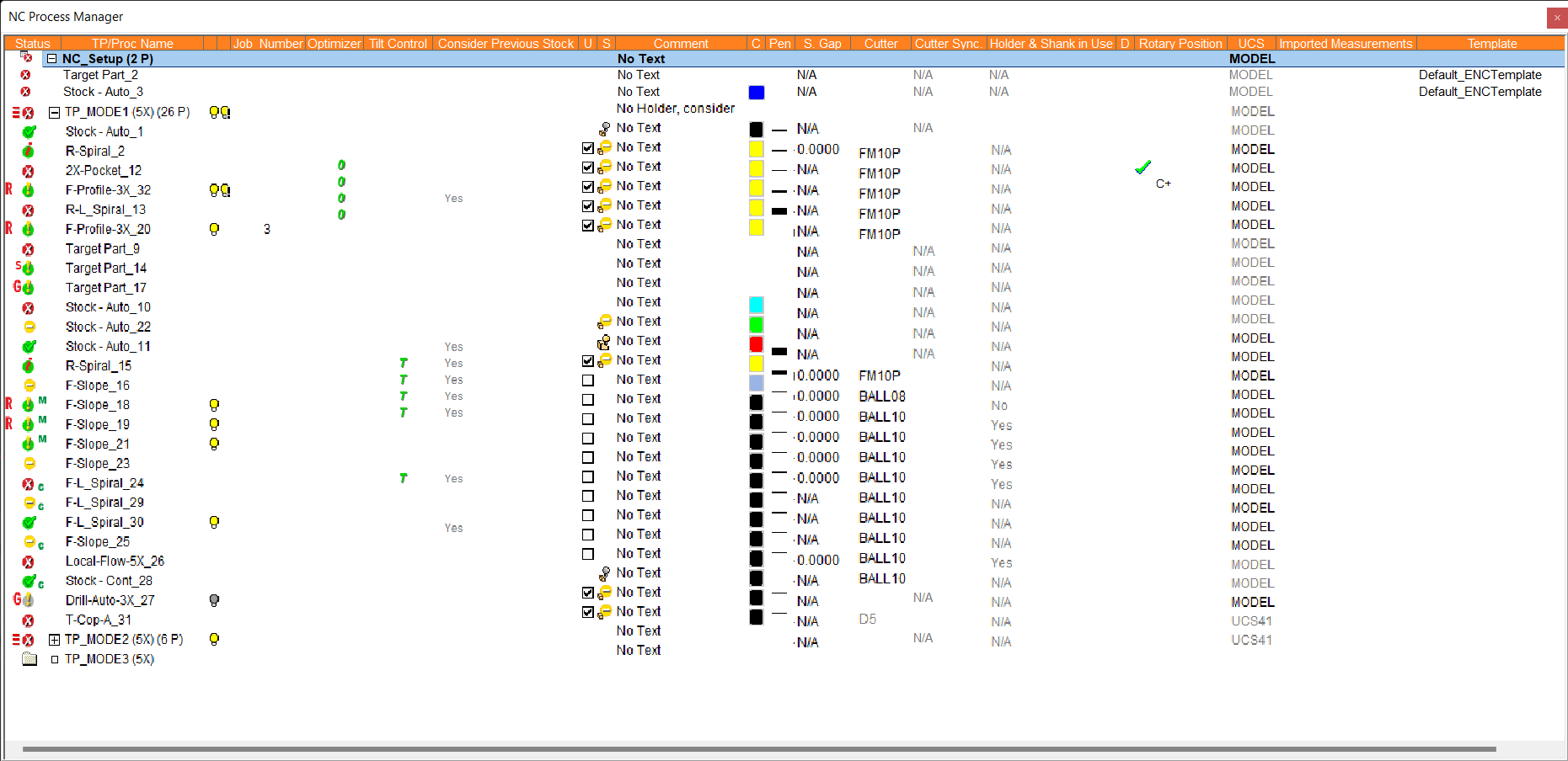
The NC Process Manager consists of a collapsible tree containing detailed information of all toolpaths and their procedures. In addition, the Process Manager displays the status of each toolpath and procedure by using status flags and symbols.
The NC Process Manager holds a large amount of information, but you can customize the display to show the items that are more important and useful to the task at hand.
Multiple Selection in the NC Process Manager
-
Non-Consecutive Selection: To select non-consecutive entries, use the Shift key together with the left mouse button.
-
Consecutive Selection: To select consecutive entries, click and hold down the left mouse button while dragging; there is no need to use the Shift or Ctrl keys. If you keep dragging past the window, the procedure list will scroll. When several procedures are selected, you can right-click the mouse to access options such as Delete or Comment for the entire selection. If you click/hold/drag the left mouse button when directly over the Process Manager light bulb icons, you can quickly hide or show many procedures on the screen at once.
Table Columns
The NC Process Manager holds a large amount of information, but you can customize the display to show the items that are more important and useful to the task at hand. Right-click the column header row of the NC Process Manager window to display the Column Chooser popup menu.

This menu enables you to select which columns are displayed out of the many columns available, each offering different information about the NC procedures on the list.
The table below shows the column heading names appearing in the Process Manager (the popup menu names are shown in parenthesis), and the column description with links to additional explanations.
Select the column name that you wish to be displayed in the Process Manager. The highlighted names (in ORANGE) are columns that are already displayed.
Note: Text items that are grayed out cannot be changed from the Process Manager.
|
NC Process Manager |
Corresponding Column Chooser Item Name |
Column Description |
||||||||||
|
Status |
(None) |
Displays the status flags and symbols of toolpaths and procedures. Position the cursor on the status flags icons to display a tooltip explaining the current status flags. |
||||||||||
|
Detailed TP/Proc Name |
Detailed TP/Proc Name |
The detailed toolpath or procedure name. Edit a procedure by double-clicking on the procedure name. This column is not displayed in the image above; see an example heresee an example here.
|
||||||||||
|
TP/Proc Name |
TP/Proc Name |
The short toolpath or procedure name. Edit a procedure by double-clicking on the procedure name. |
||||||||||
|
2D Orbit |
2D Orbit |
Displays the 2D Orbit parameter for relevant procedures where a Spark Gap parameter is used (Electrode Machining must be enabled using the setting Automatic or Advance, and the parameter is editable in the table if set to Advance). |
||||||||||
|
<empty column header> |
Motions Visibility |
Hide or Show the tool motions on a toolpath or procedure. Hide = |
||||||||||
|
<empty column header> |
Holder Prevent Areas Visibility |
Hide or Show Holder Prevent Areas. Hide = If the holder is a limiting factor and the procedure can not reach some areas, a light bulb in the Holder Prevent Areas Visibility column will appear, highlighting the portion of the toolpath that cannot be safely machined. |
||||||||||
|
Job Number |
Job Number |
Job number and job name as they appear in the Job Manager. The Job Number column shows the number of the last job containing the procedure. If the job is Not Up-to-Date, an exclamation mark is added before the job number and the cell is highlighted in yellow. The Job Name column is not displayed in the example image above. |
||||||||||
|
Job Name |
Job Name |
|||||||||||
|
Machining Time |
Machining Time |
The total machining time for the associated process. |
||||||||||
|
Optimizer |
Optimizer |
If a procedure contains optimization conditions, the |
||||||||||
|
Tilt Control |
Tilt Control |
If tilt control (5-axis inclination) is used in a procedure, the |
||||||||||
|
Consider Previous Stock |
Consider Previous Stock |
Identify whether previous stock information is considered before generating tool motions. This procedure parameter appears under the Motion Parameters > Stock parameter tree. If previous stock information is considered for a procedure, Yes appears in the relevant row of the Process Manager. |
||||||||||
|
U |
Update Stock |
Define whether or not to update the remaining stock information. The checkbox enables you easily define whether or not the procedure updates the remaining stock (see the S flag explanation below). This procedure parameter appears under the Motion Parameters > Stock parameter tree. |
||||||||||
|
S |
Remaining Stock Visibility |
Remaining Stock. An icon appears in this column if the checkbox in the U column is selected (signifying that the procedure updates the remaining stock). One of the following Remaining Stock icons may appear here, depending on the status:
|
||||||||||
|
Comment |
Comment |
Displays the current comment if any. Click the text to change a comment for single or multiple toolpaths or procedures. |
||||||||||
|
Template |
Template |
Displays the template name (and file path) from which the procedure originates. Click the template name to highlight all procedures originating from the selected template and copy, edit, delete, or change color as needed. |
||||||||||
|
C |
Color |
Displays the current colors of cutter motions; click to change the color. |
||||||||||
|
Pen |
Pen |
Define the pen size of cutter motions. |
||||||||||
|
S. Gap |
Spark Gap |
Change the Spark Gap parameter value for single or multiple procedures. |
||||||||||
|
Cutter |
Cutter |
Displays the name of the currently used cutter. Click the button to change or edit the cutter; this displays the Cutters and Holders dialog. Single or multiple procedures can be selected for the cutter change/edit operation. Note: You can easily change the cutter used by an NC procedure by simply double-clicking on the tool name in the NC Process Manager window. This opens up the Cutters and Holders dialog where you can choose any tool from your library. When the NC general preference for Allow replacing tool without suspending motions is ON, you may not be required to recalculate the toolpath and this will keep the new cutter following the original cutter motions. |
||||||||||
|
Cutter Sync Status |
Signifies if the cutter's parameters (Motion and/or Machining Parameters) have been synchronized in a procedure. The Cutter Sync column in the NC Process Manager displays one of the following statuses, depending on the procedure's parameter synchronization status:
|
|||||||||||
|
Holder & Shank in Use |
Holder & Shank in Use |
Identify whether or not the machining takes into account the Holder and Shank when performing calculations. Additionally, identify whether the Minimum Clear Length is calculated. If a holder is not used with the defined cutter, N/A is displayed. This procedure parameter appears under Motion Parameters > Stock, Shank & Holder Tracking. |
||||||||||
|
D |
Compensation |
Show if cutter compensation (also known as Diameter Compensation) has been applied. This procedure parameter appears under Machine Parameters. |
||||||||||
|
Rotary Position |
Rotary Position |
Identifies whether a Preferred Rotary Axis Position was defined for the procedure. If an axis was defined, the name of the preferred rotary axis is displayed together with the plus or minus sign to represent the negative or positive setting; for example, C+. The preferred rotary axis is defined in the Machine Parameters Table of the procedure. |
||||||||||
|
UCS |
UCS |
Displays the name of the active UCS which represents the direction of the machining calculations. Click the name to select a different UCS from a dropdown list of available options. |
||||||||||
|
Imported Measurements |
Imported Measurements |
Indicates if an On Machine Inspection (OMI) procedure has measurement results imported into it. If measurement results have been imported into an OMI procedure, Yes appears in the relevant row of the Process Manager. |
||||||||||
|
Template |
Template |
Lists the name of the template from which the component (procedure, NC Setup, toolpath folder, stock, part) originated. Hover the mouse cursor over the template name in the NC Process Manager to display its full file path. If the procedure was not defined by a template, this column is blank. |
 . Show =
  .
. . Show =
  . Holder Prevent Areas are unmachined areas that were calculated but not machined due to the holder prevention mechanism (to avoid holder collision with the part/stock). These icons are only displayed if holder prevented areas are created.

Notes:
-
Right-click on the column header row of the Process Manager to display the Column Visibility Popup menu.
-
Use the functionality in the popup submenu to set the visibility of columns in the table.