|
|
Working in NC
One NC file can be opened per Cimatron session. If an NC file is already open and you open another NC file, the second NC file is loaded in another Cimatron session. In this way, multiple NC files can be loaded in multiple Cimatron sessions.
The following links provide additional information for working in the NC environment:
|
Compare and detect changes between the active part (original) and a selected (reference) part. |
|||||
|
Create a Toolpath. A Toolpath is a sequence of one or more machining Procedures, performed in a given set of milling axes. |
|||||
|
Create a Procedure in the active toolpath. A Procedure is a set of cutter movements that conform to a specific machining technology. One or several Procedures can comprise a toolpath. |
|||||
|
Part is a 3X procedure used to represent the final-product designed part. Part is a special procedure that only contains faces; it does not contain any toolpaths. |
|||||
|
Stock is a 3X procedure used to represent the stock material from which the final part will be produced. Remaining stock is calculated after each procedure so that cutter motions can be optimized upon the current stock status. Stock is also used by the Simulator and Verifier. The remaining stock can be displayed at any time after any executed procedure (the procedure must have a |
|||||
|
Cutter Compensation allows CNC operators to use a different cutter than the one used during the programming of a procedure. It enables the CNC machine controller, at run time, to compensate for any difference between the cutter currently being used by the machine and the cutter defined in the NC operation, and/or part offset, in order to achieve accuracy. This means that the machine controller calculates the correct offset from the surface to be cut based on the available cutters. The advantage of this approach is that changes to the offset value are done directly on the machine without editing the NC code. This is useful when making changes to compensate for cutter wear, handling machining tolerances, or switching to a cutter with a different diameter. |
|||||
|
Numerous cutter-related operations can be performed from the Cutters and Holders dialog, including Cutter, Extension, and Holder management. |
|||||
|
Display, analyze and edit motions using the Navigator, Global Filter, Motion Editor and other functions. |
|||||
|
In Cimatron, Feature Based Machining (FBM) (also known as Manufacturing Feature Recognition (MFR)) is a set of capabilities used to quickly, easily, and safely program plate machining with many features. It includes feature recognition and management tools for holes, pockets and chamfers, use of sequences and pocket templates for greater automation and shop floor standardization.
|
|||||
|
Perform a range of Geometry operations on NC Procedures. A Procedure is a set of cutter movements that conform to a specific machining technology. One or several Procedures can comprise a toolpath. |
|||||
|
As part of the On
Machine Inspection procedure process, import the measurement results
file from the CNC controller back to Cimatron.
|
|||||
|
As part of the On Machine Inspection procedure process after the measurement results have been imported, create an inspection report. The report may be produced in Excel and 3D PDF formats (both formats can be created simultaneously).
|
|||||
|
The Job Manager lists all jobs. A job is defined as an execution of either Post Processing (PP) or NC Report (NCR). Each time you execute either of these functions, a new job is created capturing the session. Using the Job Manager, you can follow up the relevant data for each execution, such as the list of the participating procedures, the post-processor used, the post interaction parameters, the session time, and the output file location. The Job Manager enhances control over the milling process and results in easier management of the deliverables to the shop floor.
|
|||||
|
Load one or more models into your currently open NC file. |
|||||
|
Using the Machine Parameters dialog (in addition to the part, cutter, and holder), you can also view the entire machine and fixtures inside the NC programming environment. You can manually move the machine axes, considering the machine kinematics and travel limits, to an optimal orientation. Once found, an appropriate UCS is defined to be used for programming the procedure(s). In addition, selecting a machine simulator enables you to preview the part in the CNC machine table. |
|||||
|
Using the Machine Preview tool, in addition to the part, cutter and holder, you can also view the entire machine and fixtures, inside the NC programming environment. You can manually move the machine axes, considering the machine kinematics and travel limits, to an optimal orientation. Once found, an appropriate UCS is defined to be used for programing the procedure(s). |
|||||
|
The Machining Simulation tools offer a combined environment for machining simulation that includes the following capabilities: material removal simulation, machine simulation, and verifier. These tools enable you to simulate and verify your NC toolpaths and procedures before implementing them on the shop floor. |
|||||
|
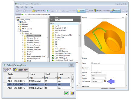
The Material Library is a tool
that enables you to define part material properties. This tool is used
throughout Cimatron
where materials need to be defined.
Material data is used in the Cimatron Explorer and NC Setup where materials can be assigned to parts and also in the Machine Parameters tab of the Cutters & Holders Dialog where the material is used to filter the appropriate cutting conditions (feed, spin, etc.) of the cutters.
The materials table can be edited when invoked from the Menu bar. Material Selection Example:Material Selection Example:
|
|||||
|
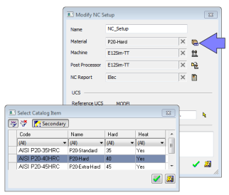
The NC Setup enables you to predefine multiple project-related options in a single place. The NC Setup contains the general data associated with a project, such as the part material, part geometry, machining orientations, fixtures, initial stock, machine name, and post processor. The data defined in the NC Setup is later used as the default for various NC operations. For example, the defined part material is used to set different machining parameters in the cutter definition. The NC Setup parameters can be edited as required. |
|||||
|
The NC Report is a file that provides various information about a set of selected procedures. This information includes details about the project and provider, as well as toolpaths, procedures (including multi-cutter information), and parameters. |
|||||
|
The Pocket Manager is a Feature Based Machining analysis function that recognizes pockets for safer and faster programming. The function automatically recognizes pocket (and slot) geometries, including open edges, and considers the height, shape, and draft angles of each pocket. The recognized pockets can be used in downstream procedures and templates and you can filter the selection by pocket attributes, such as open/closed walls, through/bottomed pocket, with or without draft angles. |
|||||
|
A Cimatron Post Processor is a program that translates Cimatron NC (Numerical Control) data (toolpaths and procedures) into specific CNCCNC machine tool commands (machine code). These commands are known as Posts or G-Code programs (see the Glossary for additional information on G-Code). |
|||||
|
Create a Procedure in the active toolpath. A Procedure is a set of cutter movements that conform to a specific machining technology. One or several Procedures can comprise a toolpath. |
|||||
|
The NC Process Manager consists of a collapsible tree containing detailed information of all toolpaths and their procedures. In addition, the Process Manager displays the status of each toolpath and procedure by using status flags and symbols. |
|||||
|
Create a Set consisting only of horizontal faces. Sets are used to create groups of specific geometric entities. In this case, horizontal faces are considered as those that are parallel to the XY plane of the active UCS. |
|||||
|
Show an entity by entering its ID number. |
|||||
|
Create a Toolpath. A Toolpath is a sequence of one or more machining Procedures, performed in a given set of milling axes. |
|||||
|
The Utility Procedure is a special type of procedure that appears in
the NC Process
Manager, among other procedures. The procedure can serve any purpose
defined during its creation, normally for sending information to the Post Processor
and the NC Report.
|
|||||
|
Perform various Wire EDM operations |

|