|
|
Transfer Die Guides

Access: To show the Die
Guide Toolbars, right-click a currently displayed toolbar and
select the appropriate Die
checkbox from the popup list of available toolbars.
To hide the toolbar, unselect the checkbox.
The following guides are available for Transfer Die:
Die Process Design Guide (Transfer Forming)
The Die Process Design Guide (Transfer Forming) menu is shown below. See the DieDesign Functions for functions that appear under the DieDesign menu.
| Die Process Design Guide (Transfer Forming) |
Function Description |
||||||||||||||||||||||||
|
|
Open the Setup table and define default parameters in the die-related tabs. |
||||||||||||||||||||||||
|
|
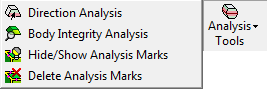
Analysis Tools. SummarySummary This group of functions is used for performing Analysis operations. The following optionsoptions are displayed.
|
||||||||||||||||||||||||
|
|
Create a Form CS (Coordinate System) on a forming shape. The Form CS is the master UCS for a forming shape part. The positioning of the parts in the forming shape assembly is defined according to this UCS. |
||||||||||||||||||||||||
|
|
This group of functions enables you to add, relocate and delete forming shapes from the strip. The following optionsoptions are displayed.
|
||||||||||||||||||||||||
|
|
Create a skin (with no thickness) from an object. This enables clear and easy analysis of operations in the system. |
||||||||||||||||||||||||
|
|
Create or edit the blank for the electrode, using finite element analysis (FEA). |
||||||||||||||||||||||||
|
|
Display analysis data such as thickness strain and safety zone ranges. This function can only be used on a file where a Blank has already been created. |
||||||||||||||||||||||||
|
|
Create flat faces from a simple given 3D model (containing planar & cylindrical faces). |
||||||||||||||||||||||||
|
|
Bend objects around an axis. |
||||||||||||||||||||||||
|
|
Unbend and flatten specific areas of the die part along cylindrical and planar faces. The length of the original faces remain the same without any changes after the unbending result is achieved. |
||||||||||||||||||||||||
|
|
Create a flat face out of a set of adjacent stitched faces using finite element analysis (FEA). |
||||||||||||||||||||||||
|
|
Geometric Manipulation. SummarySummary This group of functions is used to manipulate geometry for die design. The following optionsoptions are displayed.
|
||||||||||||||||||||||||
|
|
This group of functions provides tools for compensating springback deformation. The following optionsoptions are displayed.
|
||||||||||||||||||||||||
|
|
The following optionsoptions are displayed.
|
||||||||||||||||||||||||
|
|
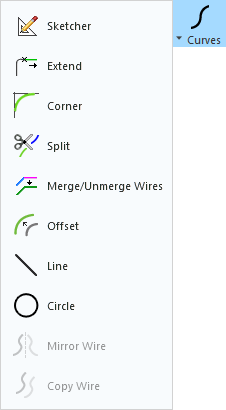
This group of functions is used for performing various operations on Curves. The following optionsoptions are displayed.
|
||||||||||||||||||||||||
|
|
Switch to Tool Design. Opens the Die Tool Design Guide (Transfer). |
Die Tool Design Guide (Transfer)
The Die Tool Design Guide (Transfer) menu is show below. See the DieDesign Functions for functions that appear under the DieDesign menu.
| Die Tool Design Guide (Transfer) |
Function Description |
|||||||||||||||||||||||||||
|
|
Open the Setup table and define default parameters in the die-related tabs. |
|||||||||||||||||||||||||||
|
|
Tools (DieDesign). SummarySummary This is a general group of tools used for die operations. The following optionsoptions are displayed.
|
|||||||||||||||||||||||||||
|
|
Analysis Tools. SummarySummary This group of functions is used for performing Analysis operations. The following optionsoptions are displayed.
|
|||||||||||||||||||||||||||
|
|
Transfer Die Sets. SummarySummary This group of functions is used in Transfer Die to define and edit the die set and station settings. The following optionsoptions are displayed.
|
|||||||||||||||||||||||||||
|
|
Trimming Punch. SummarySummary Create a trimming punch and create pockets for it in the relevant plates. |
|||||||||||||||||||||||||||
|
|
||||||||||||||||||||||||||||
|
|
Cut a part by active and parting surfaces of an opening direction. |
|||||||||||||||||||||||||||
|
|
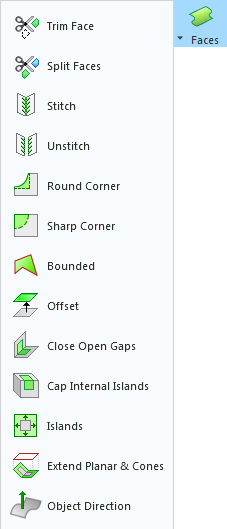
This group of functions is used for performing various operations on Faces. The following optionsoptions are displayed.
|
|||||||||||||||||||||||||||
|
|
Insert Tools (DieDesign). SummarySummary This group of functions provide a simple automated way to add inserts, and enables you to establish pockets in the core and cavity at a very early stage in design, so that time consuming wire EDM and milling operations can begin on the first day of design. The following optionsoptions are displayed.
|
|||||||||||||||||||||||||||
|
|
||||||||||||||||||||||||||||
|
|
Add Die Components. SummarySummary The following optionsoptions are displayed.
|
|||||||||||||||||||||||||||
|
|
Create an assembly BOM (Bill of Materials). This BOM file contains all the data regarding the components that make up the complete assembly. The BOM function is also available in the Drafting application to create a Bill of Materials table for the drafting sheet. |
|||||||||||||||||||||||||||
|
|
Switch to Forming. Opens the Die Process Design (Transfer Forming) Guide. |
|